Node Voltage Method Circuit Analysis With Current Sources
TLDRThe video script presents a detailed walkthrough of solving a circuit using the node voltage method. It begins by defining the circuit's components and setting up the node voltage method, applying Kirchhoff's current law and Ohm's law to calculate the electric potential at key points and the current flowing through each resistor. The process is demonstrated with two examples, showing how to handle different configurations and current sources, and emphasizing the importance of understanding voltage drops and current directions to accurately solve the circuit.
Takeaways
- 🔌 The video demonstrates the use of the node voltage method to solve a circuit with given component values and a voltage source.
- ⚡️ A voltage source of 70 volts and resistors R1 (10 ohms), R2 (5 ohms), and R3 (6 ohms) are used in the initial example.
- 🔋 An independent current source of 5 amps is also included in the circuit which influences the current flow through the resistors.
- 📌 Kirchhoff's Current Law is reviewed, stating that the sum of currents at a junction must equal zero.
- 🔄 Ohm's Law is applied to calculate the current through each resistor based on voltage across and resistance.
- 🔢 The process starts by identifying nodes and assigning the ground node a potential of 0 volts.
- 💡 Voltage at unknown nodes (VA, VB) is determined through a series of equations based on current flow and resistor values.
- 🎯 A second example is provided with an independent current source of 8 amps and resistors R1-R5, along with a 50-volt source.
- 🔍 The direction of current flow through a resistor is deduced by comparing electric potentials at different nodes.
- 🧠 A method for predicting current direction is discussed, which involves temporarily removing a resistor to observe the effect on other nodes.
- 🔏 The script concludes by solving the second example circuit, confirming the current flow and electric potential at each node.
Q & A
What is the main method used to solve the circuit in the video?
-The main method used to solve the circuit in the video is the node voltage method.
What are the values of the voltage source and the resistors in the first example?
-In the first example, the voltage source is 70 volts, R1 is 10 ohms, R2 is 5 ohms, and R3 is 6 ohms.
How is the ground node's electric potential assigned in the node voltage method?
-In the node voltage method, the ground node's electric potential is assigned a value of 0 volts.
What is Kirchhoff's Current Law as mentioned in the video?
-Kirchhoff's Current Law states that the sum of the currents at a junction must add up to zero.
How is the current flowing through R1 calculated in the first example?
-The current flowing through R1 is calculated using the voltage across R1 (70 volts - voltage at node A) divided by the resistance of R1 (10 ohms).
What is the final calculated electric potential at point A in the first example?
-The final calculated electric potential at point A in the first example is 40 volts.
How many resistors are in the second example circuit, and what are their values?
-There are five resistors in the second example circuit: R1 is 10 ohms, R2 and R3 both are 5 ohms, R4 is 4 ohms, and R5 is 10 ohms.
What is the role of the 8 amp independent current source in the second example?
-The 8 amp independent current source sends current through R1, R2, R3, and R4, influencing the electric potential at node B and the direction of current flow through R3.
How is the direction of current flow in R3 determined in the second example?
-The direction of current flow in R3 is determined by comparing the electric potentials at nodes B and C. If VC is greater than VB, the current flows from B to C; if VB is greater than VC, it flows from C to B.
What is the final calculated electric potential at node B in the second example?
-The final calculated electric potential at node B in the second example is 30 volts.
What is the final calculated electric potential at node C in the second example?
-The final calculated electric potential at node C in the second example is 20 volts.
Outlines
🔌 Introduction to Circuit Analysis using Node Voltage Method
The video begins with an introduction to solving a circuit using the node voltage method. The circuit includes a 70-volt voltage source, resistors R1 (10 ohms), R2 (5 ohms), and R3 (6 ohms), as well as a 5-amp independent current source. The goal is to calculate the current flowing through each resistor and the voltage at a specific node. The first step is to identify the nodes, with one node chosen for calculation and the ground node as the reference. The electric potential of the ground is assigned 0 volts. The video then reviews Kirchhoff's current law and Ohm's law as the foundational principles for the analysis.
📝 Calculating Currents and Voltages in the Circuit
This paragraph delves into the process of calculating the currents (i1, i2, i3) and voltages (va, vb) in the circuit. It explains how to use the voltage across resistors and Ohm's law to find the currents flowing through R1 and R2, and acknowledges the known current (5 amps) for R3. The paragraph demonstrates algebraic manipulation to solve for the electric potential at point A (va), resulting in a value of 40 volts. With this information, the video proceeds to calculate the currents i1 (3 amps) and i2 (8 amps), and confirms the consistency with Kirchhoff's current law.
🔄 Determining Current Direction in a Complex Circuit
The paragraph discusses a more complex circuit with an independent current source of 8 amps and resistors R1 (10 ohms), R2, R3, R4 (both 5 ohms), and R5 (10 ohms), along with a 50-volt voltage source. The focus is on predicting the direction of current i3 flowing between points B and C, considering the influence of both the current source and the voltage source. The video suggests a method for determining the current direction by temporarily removing R3 and comparing the electric potentials at points B and C (vb and vc). It concludes that current will flow from a higher to a lower potential, thus from B to C.
🧠 Solving for Currents and Voltages in the Modified Circuit
The paragraph continues the analysis of the modified circuit by setting up equations for the currents flowing into and out of nodes B and C. It explains the process of writing the equations based on the node voltage method and Ohm's law, considering the currents flowing towards and away from the nodes. The video then simplifies the equations, solves for the electric potentials at points B and C (vb and vc), and uses these values to calculate the currents i1 (8 amps), i2 (6 amps), i3 (2 amps), i4 (5 amps), and i5 (3 amps). The results are cross-verified with Kirchhoff's current law to ensure the correctness of the calculations.
🔧 Conclusion of Circuit Analysis
The final paragraph wraps up the circuit analysis by summarizing the calculated currents and voltages. It confirms that all the currents in the circuit have been successfully determined, and the electric potential at each point is known. The paragraph emphasizes the logical consistency of the results with the laws of physics, specifically Kirchhoff's laws, and concludes that the circuit has been thoroughly solved.
Mindmap
Keywords
💡Node Voltage Method
💡Voltage Source
💡Resistor
💡Independent Current Source
💡Kirchhoff's Current Law
💡Ohm's Law
💡Electric Potential
💡Current
💡Ground
💡Circuit Analysis
💡Potential Difference
Highlights
The video demonstrates solving a circuit using the node voltage method.
A 70-volt voltage source and resistors R1, R2, and R3 with values 10 ohms, 5 ohms, and 6 ohms are used in the example circuit.
An independent current source of 5 amps is also part of the circuit diagram.
The node voltage method involves identifying nodes and the ground as the reference node with 0 volts.
Kirchhoff's current law is复习ed, stating the sum of currents at a junction must equal zero.
Ohm's law is applied to calculate currents through resistors based on voltage across them.
The video provides a step-by-step process for calculating the electric potential at a node (VA) and currents through resistors (I1, I2, I3).
A second example circuit with an 8-amp current source and resistors R1 to R5 is introduced.
The video explains how to determine the direction of current flow in a circuit with multiple energy sources.
A technique for guessing the direction of current flow is discussed, involving the removal of a resistor (R3) to simplify the circuit analysis.
The video illustrates how to calculate the electric potential at nodes B (VB) and C (VC) using the node voltage method and Ohm's law.
The importance of understanding the relationship between high and low electric potentials and current flow direction is emphasized.
The video demonstrates solving for the currents I3, I4, and I5 in the second example circuit using node voltage analysis.
The method for checking the results using Kirchhoff's current law is explained to ensure the current entering and leaving a junction is balanced.
The video concludes by summarizing that all quantities in the circuit have been solved for, including currents in each resistor and electric potentials at each node.
A clear and methodical approach to circuit analysis using the node voltage method is provided, suitable for educational purposes.
The video serves as a comprehensive guide for those looking to understand and apply the node voltage method in circuit analysis.
Transcripts
Browse More Related Video

Kirchhoff's Voltage Law (KVL) Explained
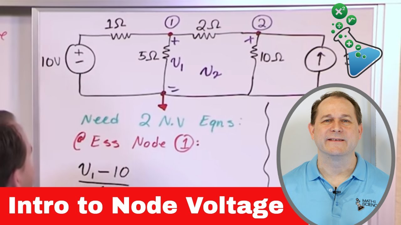
Lesson 1 - Intro To Node Voltage Method (Engineering Circuits)
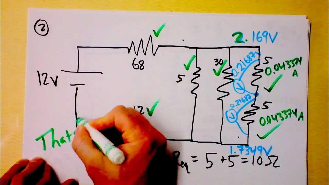
Parallel and Series Resistor Circuit Analysis Worked Example using Ohm's Law Reduction | Doc Physics
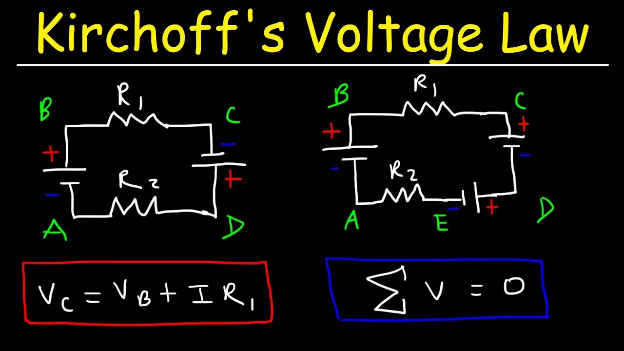
Kirchhoff's Voltage Law - KVL Circuits, Loop Rule & Ohm's Law - Series Circuits, Physics
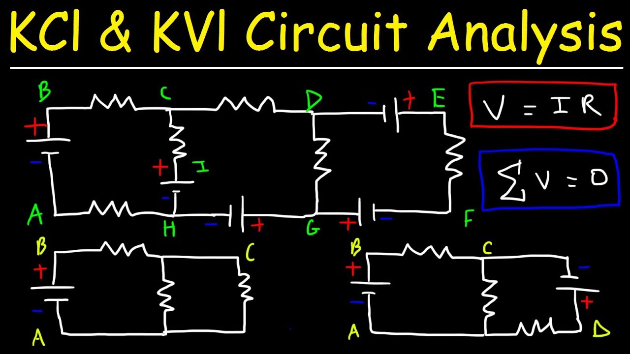
Kirchhoff's Law, Junction & Loop Rule, Ohm's Law - KCl & KVl Circuit Analysis - Physics
Series and Parallel Circuits
5.0 / 5 (0 votes)
Thanks for rating: