Series and Parallel Circuits
TLDRThis video script delves into the fundamentals of series and parallel circuits, explaining their key differences. It illustrates how current and voltage behave in each configuration and provides detailed examples of calculating current, voltage drop, and power across resistors. The script emphasizes the importance of Ohm's law and Kirchhoff's laws in circuit analysis, offering insights into energy conservation and power calculation, all while using relatable analogies for clarity.
Takeaways
- 🔋 In a series circuit, there is only one path for the current to flow, whereas in a parallel circuit, there are multiple paths.
- 💡 The brightness of light bulbs in a series circuit is dimmer compared to a parallel circuit due to the increased total resistance and decreased current.
- 📈 The total resistance in a series circuit is calculated by summing the resistances of all components (R_total = R1 + R2 + ... + Rn).
- 🔄 In a parallel circuit, the overall resistance decreases as more resistors are added, allowing more current to be drawn from the battery.
- 🔌 Ohm's Law (V = IR) is fundamental in calculating the current, voltage, and resistance in both series and parallel circuits.
- 💰 The power delivered by the battery is equal to the sum of the power absorbed by the resistors in a circuit, demonstrating the conservation of energy.
- 🚦 The voltage drop across each resistor in a series circuit adds up to the voltage of the battery, following Kirchhoff's Voltage Law.
- 🌐 The equivalent resistance of a parallel circuit can also be calculated using the reciprocal method (1/R_total = 1/R1 + 1/R2 + ... + 1/Rn).
- 🔩 The power absorbed by a resistor can be calculated in different forms: P = V*I, P = I^2*R, or P = V^2/R.
- ⏱️ The rate of energy transfer, or power, is defined as work done per unit time, measured in watts (Joules per second).
- 🔄 The current that enters a point in a circuit must equal the total current that leaves the point, in accordance with Kirchhoff's Current Law.
Q & A
What is the main difference between a series circuit and a parallel circuit?
-In a series circuit, there is only one path for the current to flow, whereas in a parallel circuit, there are multiple paths for the current to flow.
How does the total resistance change when resistors are added in series or parallel?
-In a series circuit, the total resistance increases as resistors are added, which decreases the current. In a parallel circuit, the overall resistance decreases as more resistors are added, allowing more current to flow.
What is the relationship between the current and voltage in a series circuit?
-In a series circuit, the current that flows through the resistors connected in series is the same throughout the circuit. The voltage drop across each resistor adds up to the voltage of the battery.
How can you calculate the total resistance in a series circuit?
-To calculate the total resistance in a series circuit, you simply add the resistance values of all the resistors in the series (R_total = R1 + R2 + R3 + ...).
What is Ohm's Law and how is it used in calculating the current in a circuit?
-Ohm's Law states that V = IR, where V is the voltage, I is the current, and R is the resistance. It is used to calculate the current flowing in a circuit by rearranging the formula to I = V/R.
How does the power delivered by the battery compare to the power absorbed by the resistors in a circuit?
-The power delivered by the battery is equal to the sum of the powers absorbed by the resistors in the circuit, ensuring energy conservation.
What are the different forms of the power equation?
-The power equation can be expressed in three forms: P = VI (volts times amperes), P = I^2R (current squared times resistance), and P = V^2/R (voltage squared divided by resistance).
What is the significance of Kirchhoff's Voltage Law in a circuit?
-Kirchhoff's Voltage Law states that the voltages around any closed loop in a circuit always add up to zero. It is used to verify that the sum of voltage drops and gains in a circuit equals the source voltage.
How does the voltage across resistors change in a parallel circuit?
-In a parallel circuit, the voltage across each resistor connected in parallel is the same, equal to the voltage of the power source.
What is the relationship between power and energy?
-Power is the rate at which energy is transferred or work is done. It is defined as the amount of work (energy) transferred per unit of time, measured in watts (joules per second).
How can you calculate the equivalent resistance of a parallel circuit?
-The equivalent resistance of a parallel circuit can be calculated using the formula 1/R_total = 1/R1 + 1/R2 + ... + 1/Rn, where R_total is the equivalent resistance and R1, R2, ..., Rn are the resistances of the individual resistors.
Outlines
🔌 Introduction to Series and Parallel Circuits
This paragraph introduces the concepts of series and parallel circuits, using a battery and resistors as examples. It explains that a series circuit has only one path for current to flow, while a parallel circuit has multiple paths. The video also compares the brightness of light bulbs in series and parallel circuits, noting that series circuits tend to be dimmer due to increased resistance and decreased current, while parallel circuits remain bright due to the same voltage across each bulb.
📈 Calculating Current and Voltage in Series Circuits
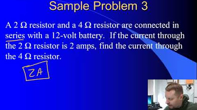
This section delves into the specifics of calculating current and voltage in series circuits. It explains how to find the total resistance by adding individual resistances and then using Ohm's law (V=IR) to calculate the current flowing through the circuit. The example provided uses two resistors with values of 4 Ohms and 6 Ohms, and a 30-volt battery. The paragraph also discusses how voltage drops across resistors in a series circuit and how they add up to the battery's voltage, in accordance with Kirchhoff's voltage law.
💡 Understanding Power in Electrical Circuits
This paragraph focuses on the concept of power in electrical circuits, defining it as the rate of energy transfer. It explains that power is measured in watts, which is joules per second, and provides an example to illustrate the difference between systems with different power outputs. The paragraph then connects back to the series circuit example, calculating the power delivered by the battery and absorbed by the resistors, demonstrating that the total power absorbed by the resistors equals the power delivered by the battery, indicating conservation of energy.
🔧 Solving a Three-Resistor Series Circuit
This part of the script presents a problem involving a series circuit with three resistors of different values (5 Ohms, 3 Ohms, and 2 Ohms) and a 60-volt battery. The paragraph explains how to calculate the total resistance and the current flowing through the circuit. It then describes how to find the voltage drop across each resistor and how these voltage drops add up to the battery's voltage, in line with Kirchhoff's voltage law. The paragraph also calculates the power delivered by the battery and absorbed by each resistor, emphasizing that the total power delivered by the battery is equal to the sum of the powers absorbed by the resistors.
🔄 Exploring Parallel Circuits with Resistors
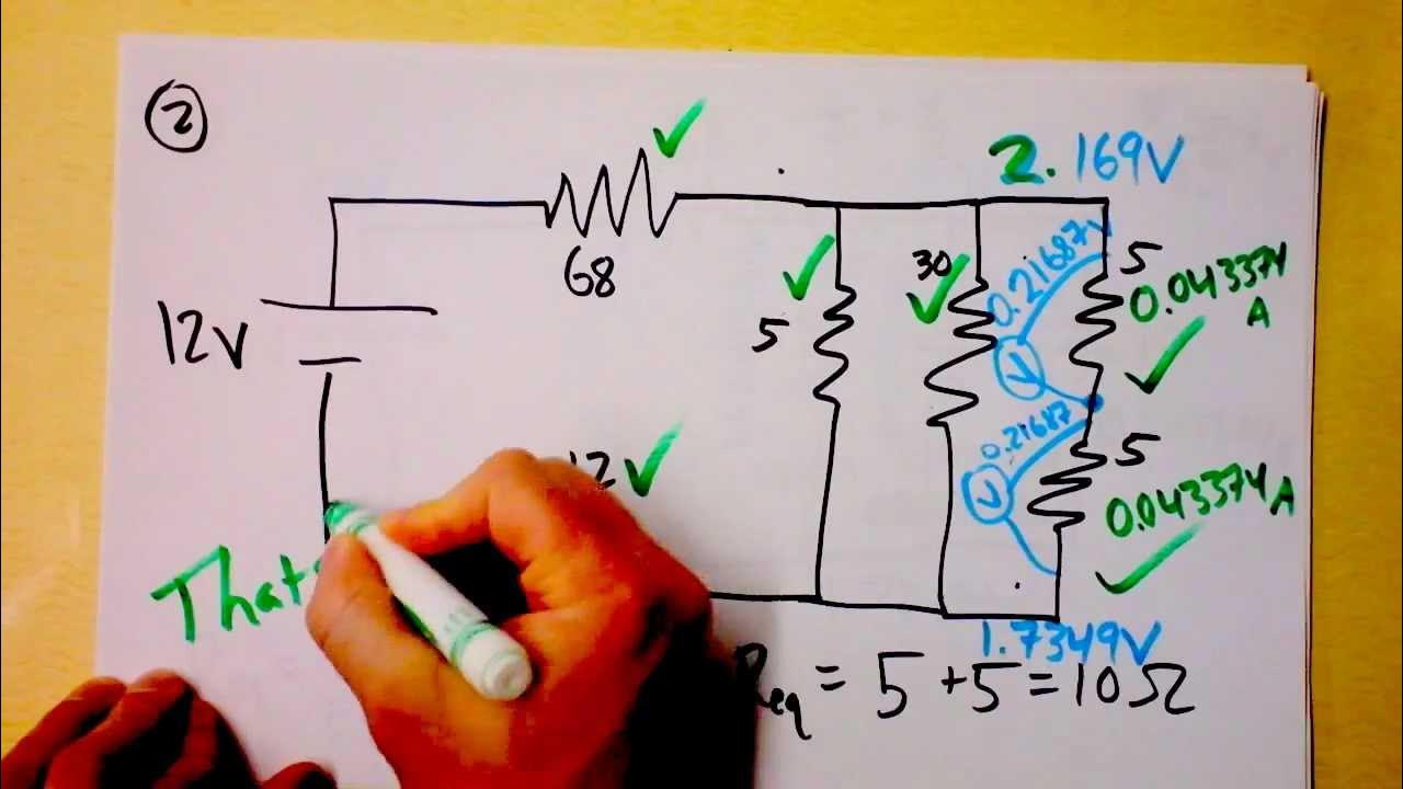
This section introduces parallel circuits, explaining that the voltage across resistors connected in parallel is the same. The paragraph calculates the current flowing through each resistor in a parallel circuit with a 24-volt battery and resistors of 6 Ohms and 8 Ohms. It then discusses how the total current leaving the battery is the sum of the currents through each resistor, aligning with Kirchhoff's current law. The paragraph concludes by calculating the equivalent resistance of the circuit and the power delivered by the battery and absorbed by the resistors.
🔌 Calculating Total Resistance and Power in Parallel Circuits
This paragraph continues the discussion on parallel circuits, focusing on calculating the total or equivalent resistance and the power delivered by the battery and absorbed by the resistors. Two methods for calculating the equivalent resistance are presented, and the power for a parallel circuit with a 20-volt battery and resistors of 2 Ohms, 4 Ohms, and 5 Ohms is calculated. The paragraph reinforces the concepts of current law and conservation of energy, showing how the total power delivered by the battery equals the total power absorbed by the resistors.
👋 Conclusion and Review of Series and Parallel Circuits
The final paragraph wraps up the video by reviewing the main points discussed. It reiterates the key differences between series and parallel circuits: in a series circuit, the current is the same through all resistors, while in a parallel circuit, the voltage across each resistor is the same. The paragraph provides a succinct summary of the concepts of current, voltage, resistance, and power in both types of circuits, highlighting the importance of understanding these fundamental principles for anyone studying or working with electrical circuits.
Mindmap
Keywords
💡Series Circuit
💡Parallel Circuit
💡Resistance
💡Current
💡Voltage
💡Ohm's Law
💡Power
💡Voltage Drop
💡Kirchhoff's Laws
💡Energy Conservation
💡Circuit Analysis
Highlights
The video explains the concepts of series and parallel circuits, using the analogy of light bulbs as resistors.
A series circuit has only one path for current to flow, whereas a parallel circuit has multiple paths.
In a series circuit, adding resistors increases total resistance, decreasing the current.
In a parallel circuit, the voltage across each resistor is the same, and adding resistors decreases total resistance.
Ohm's law (V=IR) is used to calculate the current in a series circuit with given resistor values and voltage.
The voltage drop across each resistor in a series circuit can be calculated using Ohm's law.
The power delivered by the battery and absorbed by resistors in a circuit can be calculated using the formula P=VI or P=I^2R or P=V^2/R.
The total energy absorbed by resistors should equal the power delivered by the battery, demonstrating energy conservation.
The video provides a detailed example of calculating the current, voltage drop, and power in a series circuit with two and three resistors.
The equivalent resistance of a parallel circuit can be calculated using two different methods, both resulting in the same value.
The power absorbed by individual resistors in a parallel circuit can be calculated and should sum up to the power delivered by the battery.
The video emphasizes the importance of understanding the fundamental principles of series and parallel circuits for practical applications.
Kirchhoff's voltage law is mentioned, stating that the sum of voltage drops in a closed loop must equal zero.
Kirchhoff's current law is also discussed, highlighting that the current entering a junction equals the sum of currents leaving it.
The video concludes by reinforcing the main concepts learned about series and parallel circuits, providing a comprehensive understanding for viewers.
Transcripts
Browse More Related Video

Parallel and Series Resistor Circuit Analysis Worked Example using Ohm's Law Reduction | Doc Physics

DC parallel circuits explained - The basics how parallel circuits work working principle

Ohm's Law

Electrical Formulas - Basic Electricity For Beginners

High School Physics - Series Circuits

Essential & Practical Circuit Analysis: Part 1- DC Circuits
5.0 / 5 (0 votes)
Thanks for rating: