Parallel and Series Resistor Circuit Analysis Worked Example using Ohm's Law Reduction | Doc Physics
TLDRThe script describes a complex process of solving a circuit problem involving multiple resistors. The scenario unfolds as a challenge where the protagonist is tasked with calculating the current and voltage across various resistors in a circuit powered by a 12-volt battery. The problem is approached systematically by first determining the equivalent resistances in series and parallel, and then applying Ohm's Law (V=IR) to find the current and voltage across each resistor. The solution requires understanding the principles of series and parallel circuits, as well as the distribution of current in a parallel configuration. The process is detailed, emphasizing the importance of methodical analysis and calculation in circuit design and troubleshooting.
Takeaways
- 🔌 The scenario involves solving a complex circuit problem with a variety of resistors and a 12-volt battery.
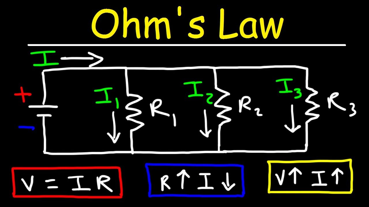
- 💡 The goal is to find the current through each resistor and the voltage across them using Ohm's Law (V=IR) and equivalent resistance concepts.
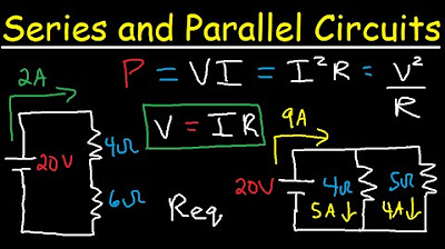
- 📊 The problem starts by identifying series and parallel resistor combinations to simplify the circuit diagram.
- 🔍 Series resistors are calculated by adding their resistances (R_total = R1 + R2 + ...), while parallel resistors are calculated using the reciprocal formula (1/R_total = 1/R1 + 1/R2 + ...).
- 🔧 The first step in solving the problem is to determine the overall resistance of the circuit to find the total current (I_total) flowing from the battery.
- 🌐 Once the total current is known, it can be distributed among the parallel paths to find the individual currents through each resistor.
- 🔽 The current forks at junctions, with different amounts of current flowing through different paths based on the resistance of each path.
- 🔄 The voltage across each resistor can be found by multiplying the current flowing through it by its resistance (V = I * R).
- 📈 The voltage drops across resistors in parallel are equal, as they are all connected to the same two points in the circuit.
- 📊 The final step is to fill in the voltage and current values for each resistor, which can be done by working backwards from the simplified circuit diagram.
- 🎓 The process requires understanding of circuit analysis, Ohm's Law, and the concepts of series and parallel resistances to solve for the various values in the circuit.
Q & A
What is the main problem presented in the script?
-The main problem is to calculate the current through and voltage across each resistor in a complex circuit with a 12-volt battery, given various resistor values.
What is the significance of simplifying the circuit diagram?
-Simplifying the circuit diagram helps to identify the combinations of resistors in series and parallel, which is crucial for calculating the overall resistance and current distribution in the circuit.
How does the speaker plan to approach the problem?
-The speaker plans to use Ohm's Law (V=IR) and the formulas for equivalent resistance in series and parallel to find the overall resistance and current in the circuit, and then break it down for each individual resistor.
What is the equivalent resistance of the two 5-ohm resistors in series?
-The equivalent resistance of the two 5-ohm resistors in series is 10 ohms, as series resistors can be simply added together.
How does the speaker calculate the total current in the circuit?
-The speaker calculates the total current in the circuit by dividing the voltage of the battery (12 volts) by the total equivalent resistance of the circuit (83 ohms), resulting in a current of 0.14458 amps.
What is the voltage drop across the 68-ohm resistor?
-The voltage drop across the 68-ohm resistor is calculated by multiplying the total current (0.14458 amps) by the resistance (68 ohms), resulting in a voltage drop of 9.8313 volts.
How does the speaker determine the voltage across the 3-ohm equivalent resistor?
-The speaker determines the voltage across the 3-ohm equivalent resistor by first calculating the voltage drop (0.43374 volts) and then subtracting it from the voltage at the previous node (2.169 volts), resulting in a voltage of 1.7349 volts.
What is the current through each of the individual resistors in the parallel branches?
-The current through each resistor in the parallel branches is calculated by dividing the voltage drop across each resistor by its resistance. For the 5-ohm resistor, it's 0.0867 amps, for the 30-ohm resistor, it's 0.01446 amps, and for the 10-ohm resistor, it's 0.00435 amps.
Why does the speaker mention that additional parallel paths decrease resistance?
-Additional parallel paths decrease resistance because they provide more avenues for the current to flow, which increases the total current in the circuit. Even though high resistance paths may have a smaller current, their combined effect is to reduce the overall resistance of the circuit.
How does the speaker conclude the problem?
-The speaker concludes that by calculating the voltage and current across each resistor using the principles of series and parallel resistances, Ohm's Law, and the concept of equivalent resistance, one can solve the complex circuit problem. The speaker emphasizes the importance of practice in understanding these concepts.
Outlines
🔌 Introduction to Circuit Analysis
The paragraph introduces a scenario where the speaker is presented with a complex circuit diagram by a stranger offering a dollar for solving it. The circuit involves multiple resistors and a 12-volt battery. The speaker aims to find the current through each resistor and the voltage across them using the principles of Ohm's Law (V=IR) and concepts of equivalent resistances in series and parallel. The speaker begins by analyzing the circuit diagram, identifying resistor values, and planning to use Ohm's Law and equivalent resistance formulas to solve the problem.
🔍 Identifying Series and Parallel Resistances
In this paragraph, the speaker starts the process of simplifying the circuit by identifying which resistors are in series and parallel. The speaker uses the equivalent resistance formulas to combine resistors in series (simply adding their values) and for resistors in parallel (using the inverse of the sum of the inverses of their values). The speaker recognizes that the resistors are not simply in series or parallel but are interconnected, making the problem more complex. The goal is to find the simplest combination of resistors to analyze first, which in this case, is the two 5-ohm resistors in series, equivalent to a 10-ohm resistor.
🧠 Solving the Circuit Step by Step
The speaker continues to simplify the circuit by identifying and calculating the equivalent resistances for parallel combinations of resistors. The speaker then moves on to slide 4, where the circuit is further simplified into a series combination of resistors. The speaker calculates the total equivalent resistance as 83 ohms and uses Ohm's Law to find the total current flowing through the circuit (0.14458 amps). The speaker then proceeds to find the voltage across each resistor by applying the current through them and using the V=IR formula. The speaker emphasizes the importance of understanding the direction of current flow and the concept of equipotential points in the circuit.
🔧 Voltage Drops and Current Distribution
The speaker delves into the concept of voltage drops across resistors and how they relate to the current flowing through them. The speaker calculates the voltage drop across each resistor using the current found in the previous step and the resistance values. The speaker also discusses the distribution of current in a parallel circuit, noting that the current prefers the path of least resistance. The speaker then calculates the current through each of the parallel resistors (0.04337 amps through the 5-ohm resistor and 0.00434 amps through the 30-ohm resistor) and notes that these currents add up to the total current in the circuit.
🎇 Final Analysis and Conclusion
The speaker concludes the analysis by revisiting the two 5-ohm resistors that were combined to form an equivalent 10-ohm resistor. The speaker calculates the voltage across each of these resistors, which is the same as the voltage across the equivalent resistor. The speaker emphasizes the importance of understanding the principles of series and parallel circuits, Ohm's Law, and the distribution of current and voltage in a circuit. The speaker successfully solves the problem by providing the current through each resistor and the voltage across them, demonstrating a thorough understanding of circuit analysis.
Mindmap
Keywords
💡resistors
💡circuit diagram
💡voltage
💡current
💡Ohm's Law
💡equivalent resistance
💡series and parallel
💡voltmeter and ammeter
💡battery
💡Ohm's Law formula
💡 equipotential
Highlights
The individual explains how to approach a complex circuit problem by breaking it down into simpler components.
A 12-volt battery powers the circuit, and the goal is to find the current through and voltage across each resistor.
The concept of equivalent resistance is introduced to simplify the analysis of the circuit.
The individual demonstrates the use of Ohm's Law (V=IR) in determining the current and voltage in the circuit.
The method for calculating series resistance is explained by simply adding the resistance values.
The process for calculating parallel resistance is detailed, involving the sum of the inverses of individual resistances.
The individual emphasizes the importance of tracking the current forks in a circuit and how they affect the overall current.
A step-by-step approach to simplifying the circuit diagram is presented, starting with the most straightforward combinations of resistors.
The concept of equipotential points in a circuit is introduced, explaining that they have the same voltage.
The individual shows how to calculate the voltage drop across a resistor using the current and resistance values.
The impact of parallel paths on the overall resistance of a circuit is discussed, noting that they decrease resistance by increasing current.
The individual provides a method for determining the voltage across each resistor in a parallel configuration.
The importance of understanding the principles of series and parallel circuits is emphasized for solving complex problems.
The individual demonstrates how to use the calculated values to fill in the voltage and current for each resistor in the original problem.
The process of solving the circuit problem is summarized, highlighting the use of Ohm's Law, equivalent resistance, and the principles of series and parallel circuits.
Transcripts


5.0 / 5 (0 votes)
Thanks for rating: