Thin Lens Equation Converging and Dverging Lens Ray Diagram & Sign Conventions
TLDRThis educational video script delves into the principles of lens optics, focusing on the lens equation and ray diagrams. It explains the properties of convex (converging) and concave (diverging) lenses, including their focal lengths and the concept of real versus virtual images. The script guides viewers through solving problems involving image location, magnification, and orientation using the thin lens equation. It also illustrates how to draw ray diagrams for different lens scenarios, providing a clear understanding of lens behavior in various setups.
Takeaways
- 🌟 The video discusses the lens equations and their application in solving optical problems and drawing ray diagrams.
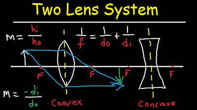
- 🔍 Two types of lenses are covered: the convex (converging) lens, which is thicker in the center and has a positive focal length, and the concave (diverging) lens, which is thinner in the center and has a negative focal length.
- 📏 Focal length is a critical concept, being the distance from the lens center to the focal point and is half the radius of curvature for a lens.
- 📚 The principal axis is a horizontal line in lens diagrams, and the focal length is measured from this axis to the lens center.
- 🔄 The terms 'object distance' (do) and 'image distance' (di) are used to describe the positions relative to the lens, with 'do' being positive when the object is to the left of the lens and 'di' being positive when the image is to the right of the lens.
- 🖼️ The nature of the image (real or virtual) is determined by the sign of 'di', with positive indicating a real image and negative indicating a virtual image.
- 🔢 The thin lens equation \( \frac{1}{f} = \frac{1}{d_o} + \frac{1}{d_i} \) and the magnification equation \( m = -\frac{d_i}{d_o} = \frac{h_i}{h_o} \) are essential for solving lens-related problems.
- 📈 Magnification indicates the size relationship between the image and the object, with a positive value for upright images and a negative value for inverted images.
- 📝 The script provides a step-by-step example using a convex lens with a focal length of 6 cm and an object placed 8 cm away, resulting in a real, inverted, and enlarged image located 24 cm from the lens.
- 🔍 The video also explores what happens when an object is placed between the lens and its focal point, resulting in a virtual, erect, and enlarged image on the same side as the object.
- 🔄 For a concave lens, regardless of the object's position, the image is always virtual, reduced in size, and upright, forming on the same side as the object.
Q & A
What are the two types of lenses mentioned in the video?
-The two types of lenses mentioned are the convex lens, also known as the convergent lens, and the concave lens, also known as the divergent lens.
What is the significance of the focal length in lenses?
-The focal length is the distance between the point F and the center of the lens. It is positive for a converging lens and negative for a diverging lens, and it is half of the radius of curvature.
What is the principal axis in the context of lenses?
-The principal axis is the horizontal line that passes through the center of the lens and is used as a reference for the positions of the object and the image.
What does it mean for a lens to have a positive or negative object distance (do)?
-A positive object distance (do) indicates that the object is placed to the left of the lens, which is typical. A negative object distance would indicate a virtual object, which is less common and can occur in a two-lens system.
What determines whether an image formed by a lens is real or virtual?
-An image is real if the light rays converge at a point, forming a real image when di is positive. If the image forms on the left side and di is negative, it is a virtual image, where the light rays appear to converge but do not actually do so.
What is the thin lens equation and what does it represent?
-The thin lens equation is 1/f = 1/do + 1/di, where f is the focal length, do is the object distance, and di is the image distance. It is used to solve problems related to the imaging properties of lenses.
How is magnification defined in the context of lenses?
-Magnification is the ratio of the height of the image (hi) to the height of the object (ho), and it is also equal to -di/do. It indicates whether the image is enlarged, reduced, or the same size as the object.
What happens to the image when an object is placed between the focal point and a convex lens?
-When an object is placed between the focal point and a convex lens, a virtual, erect, and enlarged image is formed on the same side as the object.
What is the relationship between the object's position and the type of image formed by a convex lens?
-If the object is placed beyond the focal point of a convex lens, a real, inverted, and enlarged image is formed. If the object is placed between the lens and the focal point, a virtual, erect, and enlarged image is formed.
What are the characteristics of the image formed by a concave or diverging lens?
-A concave or diverging lens always forms a virtual, erect, and reduced image, regardless of the object's position relative to the lens.
How can one determine if an image is inverted or erect?
-An image is inverted if hi is negative or if the magnification is negative, meaning the image is facing in the opposite direction to the object. It is erect or upright if hi and the magnification are positive, meaning the image is facing the same direction as the object.
Outlines
🔍 Introduction to Lens Equations and Ray Diagrams
This paragraph introduces the concept of lens equations and ray diagrams. It explains the difference between convex (converging) and concave (diverging) lenses, highlighting their focal lengths and how they affect light rays. The importance of understanding focal lengths, object distance, and image distance is emphasized. The paragraph also discusses the concept of real and virtual images, along with the orientation of the object and image. The thin lens equation and the magnification formula are introduced as essential tools for solving lens-related problems.
📚 Application of the Thin Lens Equation with a Convex Lens
The second paragraph demonstrates the application of the thin lens equation using an example of a convex lens with a focal length of six centimeters and an object placed eight centimeters away. It walks through the process of solving for the image location and magnification, explaining how to determine if the image is real or virtual, and whether it is inverted or upright. The paragraph also includes a step-by-step guide to drawing a ray diagram for this scenario and discusses the implications of the magnification value on the image size.
🔬 Exploring Image Formation with Different Object Positions
This paragraph explores how changing the object's position relative to the lens affects the image formation. It uses a convex lens with a focal length of six centimeters and an object placed four centimeters from the lens to illustrate the concept. The discussion includes solving for the image distance using the thin lens equation and determining the type of image formed (real or virtual) based on the sign of the image distance. The paragraph also addresses the magnification and the orientation of the image, leading to the conclusion that placing an object between the lens and the focal point results in an enlarged, upright virtual image.
📉 Transitioning to Diverging Lenses and Their Effects
The fourth paragraph transitions to the discussion of diverging lenses, explaining that their focal lengths are negative. Using a concave lens with a focal length of negative four centimeters and an object placed twelve centimeters away, the paragraph demonstrates the calculation of image distance and magnification. It concludes that a diverging lens always produces a virtual, reduced, and upright image, regardless of the object's position relative to the focal point.
📐 Drawing Ray Diagrams for Diverging Lenses
This paragraph focuses on drawing ray diagrams for diverging lenses, providing a visual representation of how light rays behave when passing through a concave lens. It describes the process of drawing rays that appear to diverge from the focal point and how they form a virtual image that is reduced in size and upright. The paragraph reinforces the concept that a diverging lens always results in a virtual, reduced, and upright image.
🔚 Conclusion and Summary of Lens Behaviors
The final paragraph wraps up the video by summarizing the behaviors of both converging and diverging lenses. It reiterates that a converging lens can produce real or virtual images depending on the object's position, while a diverging lens always results in a virtual, reduced, and upright image. The paragraph concludes by emphasizing the importance of understanding these concepts for solving various lens-related problems and thanks the viewers for watching.
Mindmap
Keywords
💡Convex Lens
💡Concave Lens
💡Focal Length
💡Principal Axis
💡Object Distance (do)
💡Image Distance (di)
💡Magnification (m)
💡Real Image
💡Virtual Image
💡Ray Diagram
Highlights
Introduction to the lens equations and their application in solving problems and drawing ray diagrams.
Explanation of the two types of lenses: convex (converging) and concave (diverging), with a focus on their focal lengths.
The significance of focal length in determining the behavior of light rays with respect to converging and diverging lenses.
Description of the principal axis and the concept of focal length being half the radius of curvature.
Differentiation between real and virtual images based on the object's position relative to the lens and the sign of di.
The impact of object distance (do) and image distance (di) on the formation of real and virtual images.
The role of object height (ho) and image height (hi) in determining the orientation and magnification of the image.
The thin lens equation 1/f = 1/do + 1/di and its importance in lens calculations.
The magnification equation and its relation to the image and object heights and distances.
A step-by-step example of calculating image location, height, and magnification for a convergent lens.
Ray diagram drawing techniques for lenses to visualize the path of light and formation of images.
The effect of object placement between the lens and focal point on the type of image formed.
Characteristics of images formed by diverging lenses, including their virtual, reduced, and upright nature.
The consistent outcome of virtual, reduced, and upright images with diverging lenses regardless of object placement.
Practical application of lens equations in determining image properties for various lens and object configurations.
The importance of understanding lens behavior for applications in optics and vision.
Transcripts
Browse More Related Video

Multiple Two Lens System with Diverging and Converging Lens

GCSE Physics - How to Draw Ray Diagrams #70

Ray Diagrams

Physics - Optics: Lenses (3 of 5) Lens Combinations - Converging & Diverging Lenses

Physics - Optics: Lenses (4 of 5) Lens Combinations - Converging & Diverging Lenses

Physics - Optics: Lenses (1 of 5) Lens Combinations - Two Converging Lenses
5.0 / 5 (0 votes)
Thanks for rating: