Multiple Two Lens System with Diverging and Converging Lens
TLDRThis educational video explores a two-lens optical system featuring a converging (convex) lens with a 3 cm focal length and a diverging (concave) lens with a 4 cm focal length. The script explains the thin lens equation and illustrates the process of determining image formation, orientation, and magnification for both lenses. It demonstrates that the convex lens produces a real, inverted image of the same size as the object, while the concave lens creates a virtual, upright, reduced image. The video concludes with a ray diagram to visually confirm the theoretical findings, offering a clear understanding of lens behavior in optical systems.
Takeaways
- 🔍 The video discusses a two-lens system featuring a converging (convex) lens and a diverging (concave) lens.
- 📐 The thin lens equation \( \frac{1}{f} = \frac{1}{D} + \frac{1}{Di} \) is essential for understanding image formation in lenses.
- 🌀 The focal length \( f \) is positive for a converging lens and negative for a diverging lens.
- 🔢 Given focal lengths are 3 cm for the convex lens and 4 cm for the concave lens.
- 📏 The distance between the two lenses is set to 18 cm, and the object is placed 6 cm from the convex lens.
- 📍 The first image is calculated to be at 6 cm from the convex lens, indicating a real image formed on the right side.
- 🔁 The magnification for the convex lens is 1, meaning the image is the same size as the object but inverted.
- 🔄 The image from the convex lens serves as the object for the concave lens, positioned 12 cm away from it.
- 👆 The second image produced by the concave lens is virtual, formed on the left side at a distance of 3 cm.
- 🔎 The magnification of the concave lens is 1/4, resulting in an upright, reduced image that is a quarter of the height of the first image.
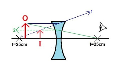
- 📝 The video concludes with a ray diagram illustrating the formation of real and virtual images by the converging and diverging lenses, respectively.
Q & A
What is the main topic of the video?
-The main topic of the video is a two-lens system involving a converging lens (convex lens) and a diverging lens (concave lens), and how to determine the properties of the images formed by these lenses.
What is the equation given in the video for lens systems?
-The equation given in the video is the thin lens equation: \( \frac{1}{f} = \frac{1}{D} + \frac{1}{Di} \), where \( f \) is the focal length, \( D \) is the distance between the object and the lens, and \( Di \) is the distance between the image and the lens.
What is the difference between a converging lens and a diverging lens?
-A converging lens, also known as a convex lens, is thicker at the center and converges light rays towards a focal point. A diverging lens, or concave lens, is thinner at the center and spreads out light rays as if they are emanating from a focal point.
What is the focal length chosen for the convex lens in the video?
-The focal length chosen for the convex lens in the video is 3 cm.
What is the magnification formula used in the video?
-The magnification formula used in the video is \( \text{Magnification} = \frac{Di}{D} \), which is also the ratio of the image height to the object height.
How does the video determine if an image is real or virtual?
-The video determines if an image is real or virtual based on the sign of \( Di \). If \( Di \) is positive, the image is real; if \( Di \) is negative, the image is virtual.
What does the video say about the orientation of the image formed by a convex lens?
-The video explains that if the magnification is negative, the image is inverted compared to the object. If the magnification is positive, the image is upright.
What is the relationship between the magnification and the size of the image?
-If the absolute value of the magnification is less than one, the image is reduced. If it is greater than one, the image is enlarged.
How does the video calculate the second image formed by the diverging lens?
-The video uses the thin lens equation for the diverging lens with a negative focal length and the distance from the first image to the second lens to calculate the second image's distance and properties.
What is the final image's orientation and size relative to the original object in the video?
-The final image, formed by the diverging lens, is upright and reduced in size relative to the original object. It is also virtual and on the same side as the diverging lens.
How does the video illustrate the behavior of light rays through the lenses?
-The video uses ray diagrams to illustrate how light rays behave when passing through the converging and diverging lenses, showing convergence to a point for a real image and apparent divergence from a point for a virtual image.
Outlines
🔍 Introduction to Two-Lens System
This paragraph introduces a two-lens optical system consisting of a converging (convex) lens and a diverging (concave) lens. The focal length, object distance, and image distance are explained using the thin lens equation. The script sets up an example with specific values for the focal lengths of the lenses (3 cm for the convex lens and 4 cm for the concave lens), the distance between the lenses (18 cm), and the object distance (6 cm). The goal is to determine the location and characteristics of the images formed by each lens, including whether they are real or virtual, upright or inverted, and their size relative to the object.
📐 Analysis of Converging Lens Behavior
The script delves into the behavior of the convex lens using the thin lens equation, where the focal length is positive. It calculates the image distance (di) for the convex lens when the object is placed at 6 cm, resulting in a real and inverted image located 6 cm from the lens on the right side. The magnification is determined to be 1, indicating the image is the same size as the object but inverted. The paragraph also explains the direction of the image formation based on the sign of di and the orientation of the image relative to the object.
🔬 Effect of Diverging Lens on the First Image
The script then discusses the effect of the concave lens on the image formed by the convex lens. It uses the thin lens equation with a negative focal length for the concave lens and calculates a new image distance (di) of -3 cm, indicating a virtual image on the left side of the lens. The magnification is found to be 1/4, suggesting the second image is reduced in size to a quarter of the original object's height. The image is upright relative to the first image, which is treated as the object for the concave lens.
📚 Conclusion on Image Formation and Ray Diagrams
The final paragraph wraps up the analysis by summarizing the characteristics of the images formed by both lenses. It emphasizes that a converging lens can produce a real image if the object is beyond the focal point, or a virtual, upright, and enlarged image if the object is between the focal point and the lens. The script also includes a brief on how to draw ray diagrams for both lenses to visualize the image formation process, ensuring the predicted locations and orientations of the images are correct.
Mindmap
Keywords
💡Two-Lens System
💡Converging Lens
💡Diverging Lens
💡Focal Length
💡Thin Lens Equation
💡Magnification
💡Real Image
💡Virtual Image
💡Upright and Inverted Images
💡Ray Diagram
💡Principal Axis
Highlights
Introduction of a two-lens system consisting of a converging and a diverging lens.
Explanation of the thin lens equation and its components: focal length (f), object distance (D), and image distance (Di).
Clarification of magnification as the ratio of image distance to object distance and its relation to image height.
Differentiation between converging (convex) and diverging (concave) lenses based on their shape and function.
Assignment of focal lengths to the lenses: 3 cm for the convex lens and 4 cm for the concave lens.
Description of the setup with a 6 cm object distance and an 18 cm distance between the two lenses.
Use of the thin lens equation to calculate the image distance for the convex lens, resulting in a positive 6 cm.
Determination that the image formed by the convex lens is a real image due to the positive Di value.
Analysis of image orientation, concluding that the image is inverted due to the negative magnification.
Calculation of the magnification for the convex lens, revealing no change in size between the object and the image.
Transition to the second lens, treating the image from the convex lens as the object for the concave lens.
Application of the thin lens equation to the concave lens, resulting in a negative Di value of 3 cm.
Identification of the second image as a virtual image due to the negative Di and its formation on the left side of the lens.
Determination of the second image's orientation as upright relative to the first image but reduced in size.
Calculation of the second image's magnification, which is 1/4 of the height of the first image.
Construction of ray diagrams to illustrate the formation of real and virtual images by the lenses.
General rules for image formation by converging and diverging lenses, including the nature of the images produced.
Conclusion summarizing the video's content on two-lens systems and their image formation properties.
Transcripts
Browse More Related Video
Thin Lens Equation Converging and Dverging Lens Ray Diagram & Sign Conventions

GCSE Physics - How to Draw Ray Diagrams #70
Physics - Optics: Lenses (3 of 5) Lens Combinations - Converging & Diverging Lenses
Physics - Optics: Lenses (1 of 4) Converging Lens
Physics - Optics: Lenses (2 of 5) Lens Combinations - Two Converging Lenses
Physics - Optics: Lenses (2 of 2) Diverging Lens
5.0 / 5 (0 votes)
Thanks for rating: