Physics 15 Torque (23 of 25) More Examples: 5 F(A)=? F(B)=? of Simple Truss
TLDRThe video script presents a comprehensive analysis of a simple truss structure, focusing on the application of torque to determine forces at various points. A truss, composed of interconnected beams or members, is assumed to be in equilibrium under a 1000 Newton force applied at the top right. The script guides through calculating the reactionary force at point B and force at A by setting the sum of torques to zero. Using trigonometry, the distances from the force lines to the pivot points are determined, which are then used to solve for the forces. The members under tension and compression are identified by the direction of the applied force. Finally, the forces of tension and compression on the members are calculated using the law of sines and vector summation at specific joints. The process involves understanding equilibrium, geometrical relationships, and the role of each member in the truss.
Takeaways
- 📐 The concept of torque is used to determine the forces at different points in a simple truss structure.
- ⚖️ The truss is assumed to be in equilibrium, with the sum of torques about a pivot point equaling zero.
- 🔩 The weight of the truss members is considered negligible compared to the force applied at the top.
- 📏 By using trigonometry, the perpendicular distances from the force lines of action to the pivot points are calculated.
- 🧮 The force at point B (F_B) is found by solving the torque equation, which involves distances and the applied force.
- ⏸ The force at point A (F_A) is determined by considering the sum of forces in the Y direction, which must also equal zero.
- 🔍 Tension and compression in truss members are identified by the direction in which they resist or push against applied forces.
- 📐 The angles between the members help determine the type of force (tension or compression) acting on each member.
- 📐 The law of sines and simple trigonometry are used to calculate the forces of tension and compression on individual members.
- 🔩 The force of tension on member 3 (F_3) is found using the force at B and the known compression forces in the other members.
- 📐 By analyzing the forces at specific joints (like joint C and joint B), the individual forces acting on each member can be determined.
Q & A
What is a simple truss and what are its components?
-A simple truss is a structure composed of beams called members that are connected at their ends to form a rigid structure. The members are typically connected in a triangular shape to provide stability.
What is the concept of torque used for in the context of a truss?
-In the context of a truss, the concept of torque is used to determine the forces acting on the members of the truss, particularly when the truss is in equilibrium. It helps to calculate the reactionary forces and the forces of tension and compression in the members.
Why is the weight of the truss members often ignored in calculations?
-The weight of the truss members is often ignored in calculations because it is usually negligible compared to the external forces acting on the truss, such as the force applied at the top.
How is the equilibrium of a truss ensured when calculating torque?
-The equilibrium of a truss is ensured when calculating torque by setting the sum of all torques about a chosen pivot point to zero. This is because if the sum is not zero, the truss would not be in equilibrium and would collapse.
What are the steps to find the force at point A (Fa) and point B (Fb) in the truss?
-To find the force at point A and point B, first, set the sum of torques about point A to zero, considering the applied force and the reactionary force at B. Then, solve for the force at B (Fb). To find the force at A (Fa), either move the pivot point to B and repeat the process or use the fact that the sum of forces in the Y direction must be zero, which allows you to calculate Fa as the difference between the applied force and Fb.
How can you determine which members of the truss are under tension and which are under compression?
-You can determine which members are under tension or compression by considering the direction in which the force is applied. Members that push back against the direction of the applied force are under compression, while those that pull in the direction of the applied force are under tension.
What is the process to find the forces of tension and compression on the members of the truss?
-To find the forces of tension and compression on the members, you can use the equilibrium condition at a joint, where the sum of all forces must add up to zero. By creating a vector diagram and applying trigonometric relationships, you can calculate the individual forces on each member.
How is the law of sines used to find the forces on the members of the truss?
-The law of sines is used to find the forces on the members of the truss by relating the ratios of the sides of a triangle to the sines of their opposite angles. When you know one side and the angles of the force triangle formed at a joint, you can solve for the unknown forces.
What is the significance of the angles in determining the forces on the members of the truss?
-The angles are significant in determining the forces on the members of the truss because they define the direction of the forces and the geometry of the force triangle formed at a joint. These angles, combined with the known forces and the law of sines or cosines, allow you to calculate the unknown forces.
How does the length of member one affect the calculation of distances d1 and d2?
-The length of member one, along with the given angles, is used to calculate the perpendicular distances d1 and d2 from the line of action of the forces to the pivot point. These distances are necessary to calculate the torques and ultimately the forces at points A and B.
What is the force of tension on member three (F3) and how is it calculated?
-The force of tension on member three (F3) is calculated using the force at B (Fb) and the known angles at the joint. By creating a right triangle with the forces and applying the cosine of the angle, F3 is found to be equal to Fb times the cosine of the angle, which in this case results in a force of 634 Newtons.
How does the process of summing up forces at a joint help in understanding the truss structure?
-Summing up forces at a joint helps in understanding the truss structure by allowing you to determine the individual forces acting on each member. This process ensures that the forces at the joint are in equilibrium, providing insight into the internal forces of the truss and its structural integrity.
Outlines
🔍 Introduction to Truss Structure and Torque Concept
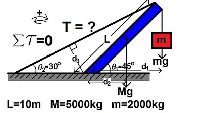
This paragraph introduces a simple truss structure consisting of three beams (members) connected at their ends to form a rigid structure. A force of 1000 Newtons is applied at the top right, and the goal is to determine the forces at points A and B, as well as which members are under tension or compression, and the magnitude of these forces. The concept of torque is used, assuming the truss's weight is negligible. The pivot point is set at point A, and the sum of torques about point A must be zero for equilibrium. The torque caused by the 1000 Newton force and the reactionary force at B is calculated using the perpendicular distances from the lines of action of these forces to the pivot point. The length of member one is given as 10 meters, and by using trigonometric functions, the distances d1 and d2 are calculated. Finally, the force at B (Fb) is solved using the equilibrium condition.
📐 Calculating Forces at A and B and Identifying Tension/Compression
The second paragraph begins by using the equilibrium condition in the Y-direction to find the force at A (Fa), which is equal to the force at B (Fb) minus 1000 Newtons. It is determined that Fa is 366 Newtons and Fb is 634 Newtons. The paragraph then explains how to identify which members are under tension or compression by pushing down on the truss's tip, causing members 1 and 2 to be under compression, while member 3 is under tension. The forces at joint C are then analyzed using a vector diagram and the law of sines to find the forces F1 and F2 acting on the truss members. F1 is calculated to be 732 Newtons, and F2 is found to be 897 Newtons, representing the compression forces on members 1 and 2, respectively.
🔩 Determining Tension in Member 3 and Summarizing Truss Analysis
In the final paragraph, the force of tension on member 3 (F3) is determined using the force at B and the known compression forces. A triangle is formed to represent the forces, and by applying trigonometric principles, F3 is calculated to be 634 Newtons. The paragraph concludes by summarizing the process of analyzing a truss structure. It emphasizes using the sum of torques about a point to find unknown forces, calculating the dimensions of the truss, and then using the sum of forces at joints to determine individual forces. This systematic approach allows for a comprehensive understanding of the forces acting on each member of the truss.
Mindmap
Keywords
💡Torque
💡Truss
💡Equilibrium
💡Tension
💡Compression
💡Force
💡Pivot Point
💡Reactionary Force
💡Member
💡Trigonometry
💡Joint
Highlights
The concept of torque is used to analyze a simple truss structure.
The truss is assumed to be in equilibrium with negligible self-weight.
A force of a thousand Newtons is applied at the top right of the truss.
The goal is to determine the force at points A and B, and the state of tension or compression in the members.
The sum of torques about point A must be zero for equilibrium.
The perpendicular distances from the forces to the pivot point are calculated using trigonometry.
The height and distances d1 and d2 are determined using the length of member one and given angles.
The force at B (Fb) is calculated using the torque equation and known distances.
The force at A (Fa) is found by considering the sum of forces in the Y direction.
Members 1 and 2 are identified as under compression, while member 3 is under tension.
The forces of tension and compression on the members are determined using vector summation at joint C.
Geometry and trigonometry are applied to find the individual forces F1 and F2 on members 1 and 2.
The force of tension on member 3 (F3) is calculated using the force at B and the cosine of 45 degrees.
The problem-solving approach involves using torque, force summation, and trigonometry to analyze truss structures.
The process demonstrates how to handle truss analysis by finding forces at specific points and the nature of forces on members.
The analysis concludes with the determination of all necessary forces acting on the truss members.
Transcripts
Browse More Related Video
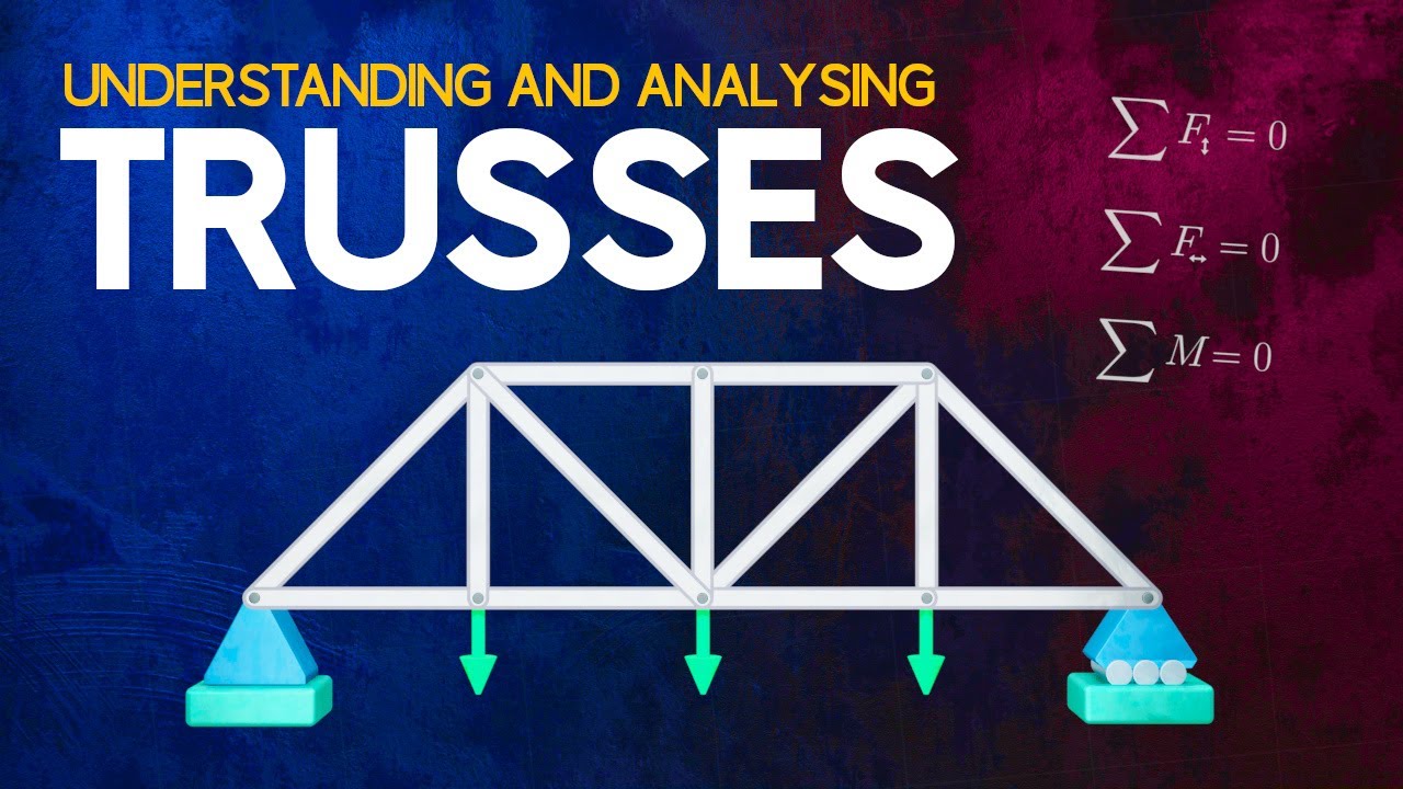
Understanding and Analysing Trusses
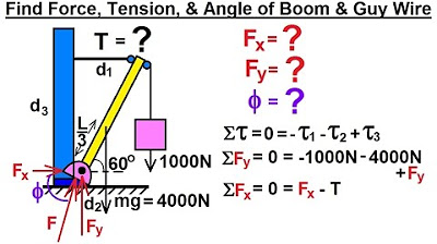
Physics 15 Torque (1 of 27) Boom and Guy Wire
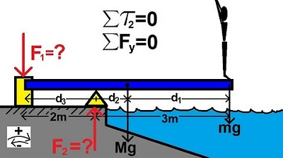
Physics 15 Torque Example 4 (4 of 7) The Diving Board
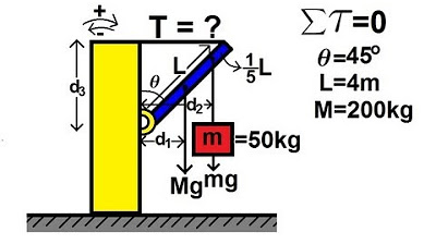
Physics 15 Torque Example 2 (2 of 7) Mass on Rod and Cable
Physics 15 Torque Example 3 (3 of 7) Mass on Rod and Cable
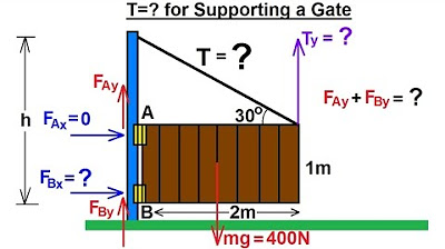
Physics 15 Torque (5 of 27) Tension=? Supporting a Gate
5.0 / 5 (0 votes)
Thanks for rating: