Circuits Grade 10 | Calculations
TLDRThe video script is an educational lesson on electrical circuits, focusing on calculations involving voltage (V), current (I), and resistance (R). It introduces the concept of series and parallel circuits, explaining how to use the VIR formulas to calculate different electrical values. The lesson progresses from basic to more complex scenarios, including a mix of series and parallel circuits, and emphasizes the importance of matching the correct voltage and resistance values. The use of ammeters and voltmeters in determining current and voltage is also discussed.
Takeaways
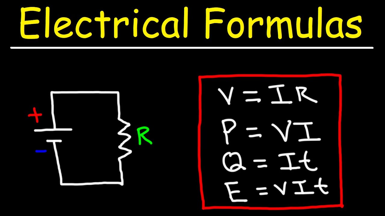
- 📚 The lesson focuses on using calculations for electrical circuits, emphasizing the importance of the Ohm's Law formula (V=IR).
- 🔌 When calculating current (I), voltage (V), and resistance (R), it's crucial to identify which components are connected in series or parallel within the circuit.
- 🔄 In series circuits, the current (I) remains constant throughout the circuit, and resistors are added together to find the total resistance.
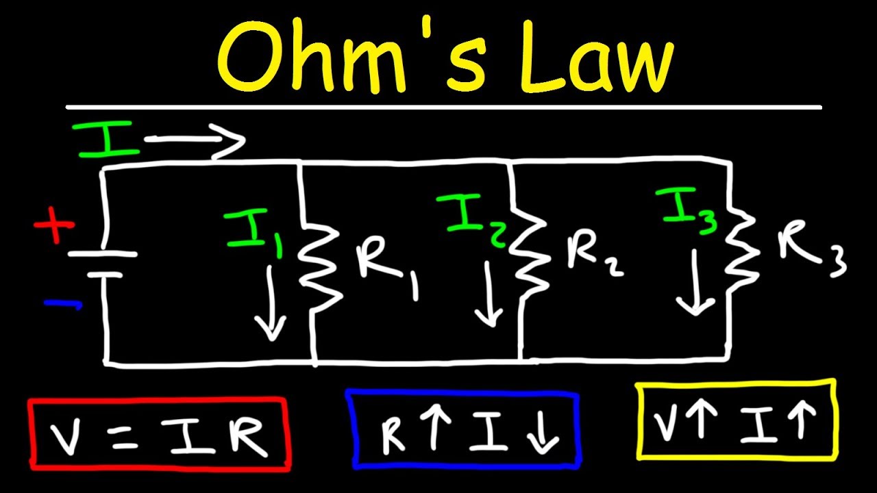
- 🔄 In parallel circuits, the voltage across each branch is the same, and the total resistance is calculated using the reciprocal formula (1/R_total = 1/R_1 + 1/R_2 + ...).
- 📈 To find the voltage across a resistor (V), multiply the current flowing through it by its resistance (V=I*R).
- 📊 To calculate the current flowing through a resistor (I), use the formula I=V/R, ensuring that the voltage (V) and resistance (R) are correctly matched.
- 🔧 When dealing with complex circuits, break down the problem by analyzing series and parallel components separately before combining them to find the total current or voltage.
- 🔋 The total voltage supplied by a battery in a circuit is the sum of the voltages across all series components and each parallel branch.
- 🔍 To solve for an unknown resistor's value (R), use the formula R=V/I with the appropriate voltage and current values from the circuit.
- 🎯 Always verify that the components used in the formulas (V, I, R) are part of the same path within the circuit to avoid errors.
- 📈 The lesson gradually increases in complexity, starting with basic circuits and progressing to more intricate setups involving both series and parallel components.
Q & A
What is the main electrical calculation formula used in the lesson?
-The main electrical calculation formula used in the lesson is Ohm's Law, which is V = I * R, where V stands for voltage, I for current, and R for resistance.
How is the ammeter (A) related to the other components in the electrical circuit?
-The ammeter (A) measures the current (I) in the circuit. It is related to the other components as it is connected in series with them, allowing the current to flow through it and providing a reading of the current flowing through the circuit.
What is the significance of resistors being in series in an electrical circuit?
-When resistors are in series, their resistances add up, which affects the total resistance in the circuit. Additionally, the current flowing through each resistor in series remains constant, as current does not split when passing through components in series.
How do you calculate the total resistance in a series circuit?
-To calculate the total resistance in a series circuit, you simply add up the individual resistance values of all the resistors connected in series. For example, if you have a 3 Ohm resistor and a 6 Ohm resistor in series, the total resistance would be 3 + 6 = 9 Ohms.
What happens to the current when resistors are connected in parallel in a circuit?
-In a parallel circuit, the current splits among the parallel paths. The total current in the main circuit is the sum of the currents in each parallel branch. Additionally, the voltage across each parallel path is the same.
How do you calculate the equivalent resistance of two resistors connected in parallel?
-To calculate the equivalent resistance (R_parallel) of two resistors connected in parallel, you use the formula: 1 / R_parallel = 1 / R1 + 1 / R2. Then, to find R_parallel, you take the reciprocal of the sum.
What is the relationship between voltage and current in a series circuit?
-In a series circuit, the voltage drop across each component is proportional to its resistance. The sum of the voltage drops across all components in series equals the total voltage supplied by the power source. The current remains constant throughout the series circuit.
How do you calculate the total voltage supplied by a battery in a circuit with series and parallel components?
-The total voltage supplied by a battery in a circuit with series and parallel components is the sum of the voltages across all series components and the voltages across each parallel branch. In the case of parallel branches, you only add one of them as they all have the same voltage.
What is the significance of the battery's EMF in the context of the circuit?
-The EMF (Electromotive Force) of a battery is the voltage that drives the current through the circuit. It is equivalent to the battery's voltage and represents the energy provided by the battery to move the charges around the circuit. In the context of the circuit, it is the total voltage that must be accounted for when calculating voltage drops across components.
How do you calculate the current flowing through a specific resistor in a parallel circuit?
-To calculate the current flowing through a specific resistor in a parallel circuit, you use Ohm's Law (I = V / R), where V is the voltage across that specific resistor and R is its resistance. You must ensure that the voltage and resistance correspond to the same parallel branch.
What is the sum of the currents in a parallel circuit?
-The sum of the currents in a parallel circuit is equal to the current in the main circuit. This is because the main circuit current is the total current flowing into the parallel section, which then divides among the parallel branches. The sum of the currents in each branch is the total current flowing out of the parallel section.
Outlines
📚 Introduction to Electrical Circuit Calculations
The paragraph introduces the concept of using calculations in understanding electrical circuits. It explains the significance of a particular triangle formula (V-I-R) for calculating voltage (V), current (I), and resistance (R). The lesson emphasizes the importance of selecting the correct values for V, I, and R based on their connection in the circuit, whether in series or parallel. The introduction also sets the stage for more complex calculations involving series and parallel circuits, promising a gradual increase in difficulty.
🔍 Applying Formulas in Series Circuits
This paragraph delves into applying the V-I-R formula in series circuits. It explains how to calculate current (I) using the formula I=V/R, emphasizing the need to match the correct voltage (V) and resistance (R) values. The example provided involves a simple series circuit with a battery voltage of 6V, resistors of 3 ohms and 2 ohms, and demonstrates how to calculate the current flowing through the circuit. The paragraph also introduces the concept of total resistance in series and how it affects the current flow, leading to the calculation of voltage across individual resistors.
🔧 Calculating Resistance and Voltage in Parallel Circuits
The focus of this paragraph is on calculating resistance and voltage in parallel circuits. It begins by explaining the formula for total resistance in parallel (1/R_parallel = 1/R_1 + 1/R_2) and how to calculate the current (I) using the battery voltage. The example provided involves a parallel circuit with two resistors and demonstrates how to find the equivalent resistance and the current flowing through each resistor. The paragraph also explains how to calculate the voltage across each resistor in a parallel circuit, noting that all resistors in parallel have the same voltage.
🌐 Understanding Series and Parallel Combinations
This paragraph explores the combination of series and parallel circuits. It explains how to calculate current (I) and voltage (V) when a circuit has both series and parallel components. The example given involves a circuit with a parallel section followed by a series section. The paragraph details the process of calculating the current in the parallel section, the voltage across the series resistor, and the total voltage supplied by the battery. It also highlights the concept that current in series remains constant, while the resistance in parallel is calculated as the reciprocal of the sum of the reciprocals of individual resistances.
📈 Solving Complex Circuit Problems
The paragraph presents a more complex scenario with a mix of series and parallel circuits. It explains how to approach problems that involve calculating various circuit parameters, such as current (I), voltage (V), and resistance (R). The example provided is a circuit with a parallel section and a series section, where the current分流 into different paths is considered. The paragraph emphasizes the importance of understanding the flow of current and the correct application of Ohm's Law in these more intricate circuits. It also introduces the concept of equivalent resistance and how to calculate it for a combination of series and parallel components.
🔌 Advanced Circuit Analysis with Mixed Configurations
This paragraph continues the exploration of mixed series and parallel circuits, focusing on advanced analysis techniques. It provides a detailed example of a circuit with a parallel section followed by a series section, including a device in series. The paragraph explains how to calculate the current flowing through specific branches, the voltage across resistors, and the total voltage supplied by the battery. It also covers the concept of voltage division in series circuits and how to calculate the resistance of individual components based on known values. The summary emphasizes the importance of methodical problem-solving and the application of electrical principles to complex circuit configurations.
Mindmap
Keywords
💡Electricity
💡Circuits
💡Ohm's Law
💡Series Circuits
💡Parallel Circuits
💡Voltage
💡Current
💡Resistance
💡Ammeters
💡Voltmeters
Highlights
Introduction to electrical circuit calculations.
Explanation of the importance of the V-I-R triangle in electrical circuit analysis.
Basic formula for calculating voltage (V) in a circuit.
Basic formula for calculating current (I) in a circuit.
Basic formula for calculating resistance (R) in a circuit.
Explanation of series circuits and their impact on current.
Example of calculating current (I) using Ohm's Law in a simple series circuit.
Explanation of parallel circuits and their impact on voltage.
Example of calculating voltage (V) across a resistor in a parallel circuit.
Introduction to the concept of resistance in series and how to calculate total resistance.
Example of calculating current (I) using total resistance in a series circuit.
Explanation of how to calculate voltage (V) across individual components in a series circuit.
Introduction to the concept of current conservation in series circuits.
Example of calculating resistance (R) using a given voltage and current in a series circuit.
Explanation of the relationship between battery voltage and the voltages across components in a series circuit.
Example of calculating current (I) in a parallel circuit using the voltage of the battery and total resistance.
Explanation of how to calculate the current in each branch of a parallel circuit.
Example of calculating the total current (A1) in a circuit with both series and parallel components.
Explanation of the concept of EMF (electromotive force) and its equivalence to battery voltage.
Example of calculating the voltage across a resistor in a circuit with a mix of series and parallel components.
Final example illustrating the calculation of various electrical quantities in a complex circuit with series and parallel elements.
Transcripts
Browse More Related Video


5.0 / 5 (0 votes)
Thanks for rating: