Circuit Analysis: Crash Course Physics #30
TLDRThe video explains circuit analysis, the process of studying components in an electrical circuit to determine voltage, current, and resistance. It covers resistors in series and parallel, using equations to calculate equivalent resistance. Then it shows how to analyze a complex circuit step-by-step, simplifying sections and determining values across all components. It relates these concepts to appreciating the workings of holiday lights. Finally, it introduces using voltmeters and ammeters to measure voltage and current when physically constructing circuits.
Takeaways
- 😀 You can use physics concepts like electricity to understand things around you, like holiday lights
- 😮 Circuit analysis lets you study components of a circuit to understand the whole system
- 💡Voltage, current and resistance are connected by Ohm's law
- 🔌 You can combine resistors in series and parallel
- 🤓 Simplifying complex circuits makes them easier to analyze
- 🔬 Measuring voltage and current confirms your analysis
- 😵💫 Be careful not to damage meters when connecting them
- 👩🔬 Modeling one resistor as equivalent to many is useful
- 🔋 Batteries provide energy to power holiday lights!
- 🌟 Appreciating physics leads to lighting game improvements
Q & A
What is circuit analysis and why is it important?
-Circuit analysis is the process of breaking down a circuit into its key components and studying each one to determine properties like voltage, current, and resistance. It's important because once you know two of those values, you can use Ohm's law to calculate the third. This allows you to analyze the circuit as a whole.
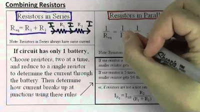
How do you find the equivalent resistance of resistors in series versus parallel?
-For resistors in series, you add up all the resistances. For resistors in parallel, you use the equation 1/R equivalent = 1/R1 + 1/R2 + 1/R3, where R1, R2, R3 are the resistances of the individual resistors.
What is the key difference between series and parallel resistor configurations?
-In series configurations, the resistors share the same current but have different voltage drops. In parallel configurations, the resistors have the same voltage drop but different currents flowing through each branch.
Once you've simplified a circuit down to one equivalent resistor, how can you analyze the rest of the circuit?
-Once you know the equivalent resistance, you can use Ohm's law to calculate the total current in the circuit. Then you can expand the circuit again, using the known current and resistances to calculate voltages and currents through each individual resistor.
How do you measure voltage in a circuit without altering it?
-You can use a voltmeter, which has a very high resistance. By connecting it in parallel across a component, it draws negligible current and allows you to measure the voltage without changing the circuit.
How do ammeters allow you to measure current without altering the circuit?
-Ammeters have a very low resistance, close to zero ohms. By placing one in series in the circuit path, it does not impede the flow of current but allows you to directly measure how much current is flowing.
If you physically constructed this example circuit, how could you confirm your mathematical analysis is correct?
-You could use a voltmeter across resistors to measure voltage drops and compare to calculated values. You could also use an ammeter in series to measure current at different points and verify the values match your analysis.
What happens if you incorrectly connect a voltmeter in series or an ammeter in parallel?
-Putting a voltmeter in series introduces too much resistance, stopping current flow. Putting an ammeter in parallel provides a very low resistance path so almost all current flows through that, possibly damaging the meter.
What conservation principle must always be satisfied at junction points in a circuit?
-Conservation of charge - the total current flowing into a junction must equal the total current flowing out. This provides a way to check your analysis.
How could analyzing holiday light circuits help improve someone's holiday lighting displays?
-By using circuit analysis, you could determine exactly how much current is required, select appropriate wire gauges, add fuses if needed, and arrange lights optimally to distribute voltage and prevent overheating.
Outlines
🤓 Understanding Electricity Through Circuit Analysis
Paragraph 1 introduces the concept of using circuit analysis to understand electricity, relating it to holiday lights. It explains the key electrical properties of voltage, current, and resistance, and how they are connected through Ohm's law. Using these concepts and equations, one can analyze any circuit configuration to determine values like current, voltage drops, etc.
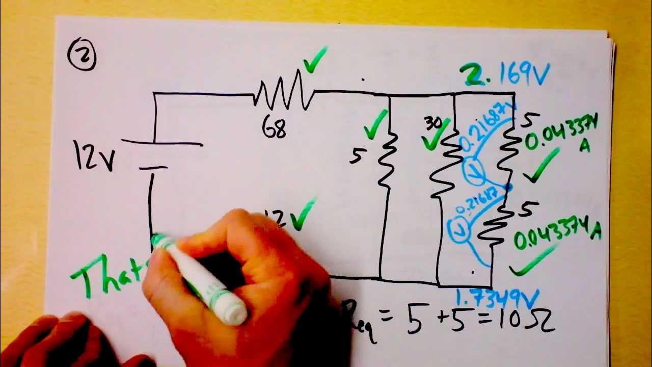
😊 Step-by-Step Circuit Analysis Example
Paragraph 2 walks through a detailed example of analyzing a complex circuit with resistors in series and parallel. It methodically simplifies the circuit into an equivalent resistor using known equations, determines the current, then expands the circuit again to calculate all voltage drops and currents through each component.
📡 Measuring Voltage and Current in Circuits
Paragraph 3 explains how to physically measure voltage and current in a circuit using voltmeters and ammeters. It describes how to properly connect these devices to avoid interfering with the circuit, and how they can be used to confirm calculated values or gain hands-on understanding of Ohm's law.
Mindmap
Keywords
💡circuit analysis
💡voltage
💡current
💡resistance
💡Ohm's Law
💡series circuits
💡parallel circuits
💡voltmeter
💡ammeter
💡equivalent resistance
Highlights
Circuit analysis breaks down circuits into key components to study each one and see what it says about the others.
If you know two of voltage, resistance and current, you can use Ohm's law to calculate the third.
Series circuits have resistors along the same path, sharing the current. Parallel circuits have resistors branching out, all with the same voltage drop.
To find equivalent resistance for series circuits, add the resistances. For parallel, use the parallel resistance equation.
Simplified the complex circuit down to one resistor to easily calculate the current drawn from the battery.
With the circuit current, we can expand back out and calculate voltages/currents through each original resistor.
For series resistors, larger resistance means larger voltage drop required.
What goes into a junction must come out to satisfy conservation of charge.
Voltmeters measure voltage without altering the circuit by having a very high resistance.
Ammeters measure current with near-zero resistance when connected in series.
Be very careful not to wrongly connect voltmeters and ammeters.
Meters allow confirming calculations and seeing Ohm's law physically.
Analysis works for any DC circuit with series and parallel resistors.
Used Ohm's law to go from equivalent circuit to every voltage and current.
Voltmeters and ammeters correctly used let you measure principles.
Transcripts
Browse More Related Video


5.0 / 5 (0 votes)
Thanks for rating: