Faraday's & Lenz's Law of Electromagnetic Induction, Induced EMF, Magnetic Flux, Transformers
TLDRThis video explores Faraday's Law of Electromagnetic Induction and Lens Law, demonstrating how a changing magnetic field induces current in a coil. It covers the effects of magnet movement, speed, and angle on induced current, and introduces the concept of magnetic flux and its relationship with induced EMF. The video also discusses Lenz's Law, the right-hand rule, and practical examples of induced current in various scenarios, including transformers and inductors.
Takeaways
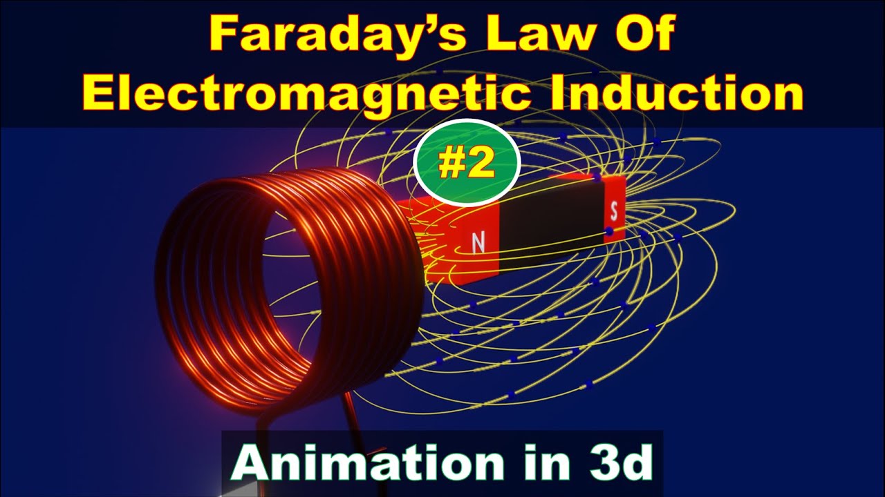
- 🌐 Faraday's Law of Electromagnetic Induction states that an electromotive force (emf) is induced in a coil when there is a change in magnetic flux, which can be caused by moving a magnet or changing the coil's area or orientation.
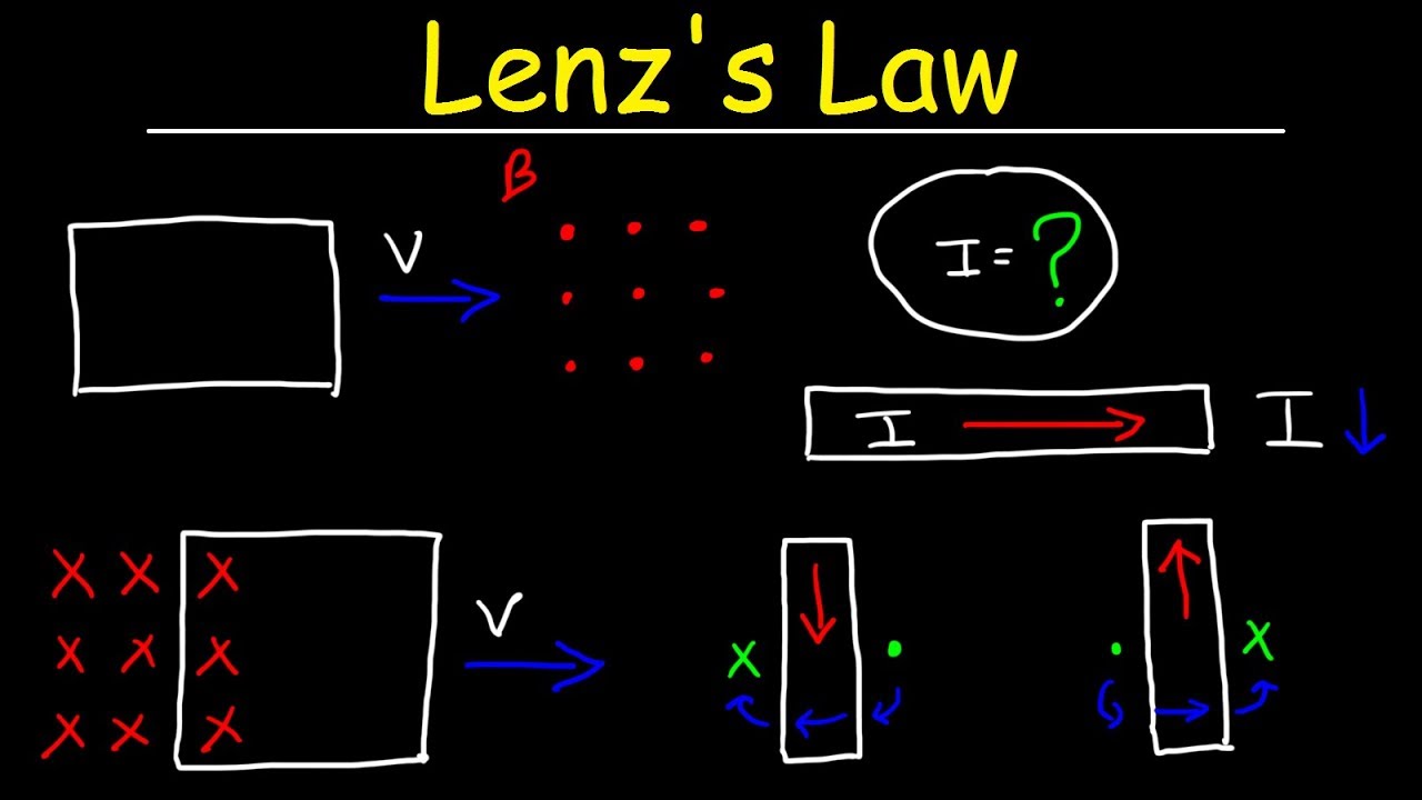
- 🧲 The direction of the induced current is determined by Lenz's Law, which states that the induced current will generate a magnetic field that opposes the change in magnetic flux that created it.
- 🔄 The magnitude of the induced emf is proportional to the rate of change of magnetic flux, meaning that faster changes in the magnetic field will result in a larger induced emf.
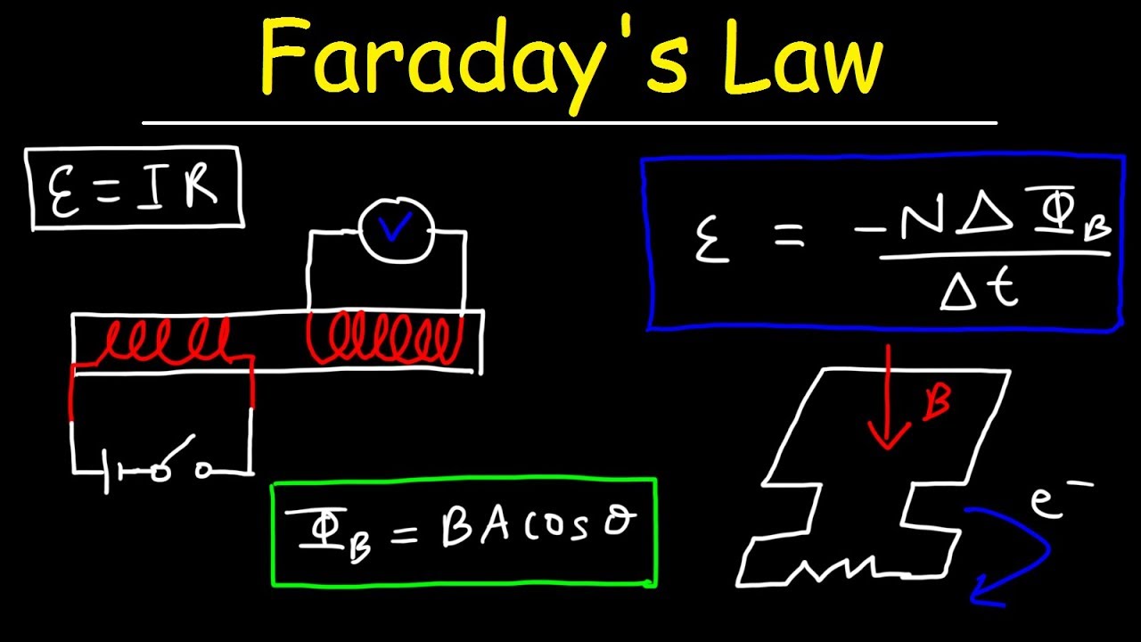
- 📊 The magnetic flux, measured in webers, is calculated as the product of the magnetic field, the area through which it passes, and the cosine of the angle between the field and the normal to the surface.
- 🔌 Transformers utilize the principles of electromagnetic induction to either step up or step down voltages, with the voltage and current ratios being inversely proportional to the number of turns in their primary and secondary coils.
- ⚡ The power transferred in an ideal transformer remains constant between the primary and secondary sides, assuming 100% efficiency, due to the conservation of energy.
- ⚙️ Inductance is a property of an electrical coil that opposes changes in current. It is calculated using the formula \( L = \mu_0 \frac{N^2 A}{l} \), where \( \mu_0 \) is the permeability of free space, \( N \) is the number of turns, \( A \) is the area of the coil, and \( l \) is the length of the solenoid.
- 🔋 The potential energy stored in an inductor can be calculated using the formula \( \frac{1}{2} L I^2 \), where \( L \) is the inductance, and \( I \) is the current.
- 📚 The energy density of a magnetic field, measured in joules per cubic meter, can be found using the formula \( \frac{B^2}{2\mu_0} \), where \( B \) is the magnetic field strength.
- 🔍 The number of turns per meter in a solenoid can be found by rearranging the inductance formula and solving for \( n \), the number of turns per unit length.
Q & A
What is Faraday's Law of Electromagnetic Induction?
-Faraday's Law of Electromagnetic Induction states that the induced electromotive force (emf) in a closed loop is proportional to the rate of change of magnetic flux through the loop. It is the fundamental principle that explains how a changing magnetic field can induce an electric current in a conductor.
How does the direction of the induced current change when a magnet is moved into or out of a coil?
-When a magnet is moved into a coil, the induced current flows in a counterclockwise direction. Conversely, when the magnet is moved away from the coil, the direction of the induced current reverses and flows in a clockwise direction. This change in direction is due to Lenz's Law, which states that the induced current will always flow in a direction that opposes the change in magnetic flux.
What is the relationship between the speed of the magnet and the induced current?
-The induced current is directly proportional to the speed at which the magnet moves into or out of the coil. A slower movement results in a smaller induced current, while a faster movement results in a larger induced current. This is because the rate of change of magnetic flux, which determines the induced emf, increases with the speed of the magnet.
What is the formula for magnetic flux and what are its units?
-The magnetic flux (Φ) is given by the formula Φ = B * A * cos(θ), where B is the magnetic field, A is the area through which the field lines pass, and θ is the angle between the magnetic field and the normal to the area. The unit for magnetic flux is the weber (Wb), which is equivalent to one tesla times one square meter.
How does changing the area of the coil affect the induced current?
-Changing the area of the coil (either by stretching or bending it) can induce a current. This is because a change in the area of the coil results in a change in the magnetic flux, which in turn induces an emf and hence a current, according to Faraday's Law of Induction.
What is the significance of the angle between the magnetic field and the coil in inducing a current?
-The angle between the magnetic field and the normal to the plane of the coil affects the magnetic flux and hence the induced current. When the magnetic field is perpendicular to the coil (θ = 90°), the cosine of the angle is zero, and no flux passes through the coil, resulting in no induced emf or current. The maximum flux and induced emf occur when the magnetic field is parallel to the normal of the coil (θ = 0° or 180°).
What is Lenz's Law and how does it relate to the direction of the induced current?
-Lenz's Law states that the induced electromotive force (emf) always gives rise to a current whose magnetic field opposes the original change in flux. This means that the direction of the induced current will be such that it tries to oppose the change in magnetic flux that produced it, either by increasing or decreasing the flux depending on the situation.
How does the number of turns in a coil affect the induced emf?
-The induced emf is directly proportional to the number of turns (n) in the coil. This is expressed in Faraday's Law of Induction as emf = -n * (ΔΦ/Δt). Therefore, increasing the number of turns in a coil will increase the induced emf for the same rate of change of magnetic flux.
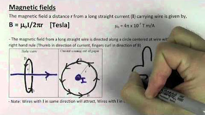
What is the role of the right-hand rule in determining the direction of the induced current?
-The right-hand rule is used to determine the direction of the magnetic field around a current-carrying conductor. When applying the right-hand rule to a coil, if you point your thumb in the direction of the current, your fingers will curl in the direction of the magnetic field lines. This helps in determining the direction of the induced current and the magnetic field it generates, especially in the context of Lenz's Law.
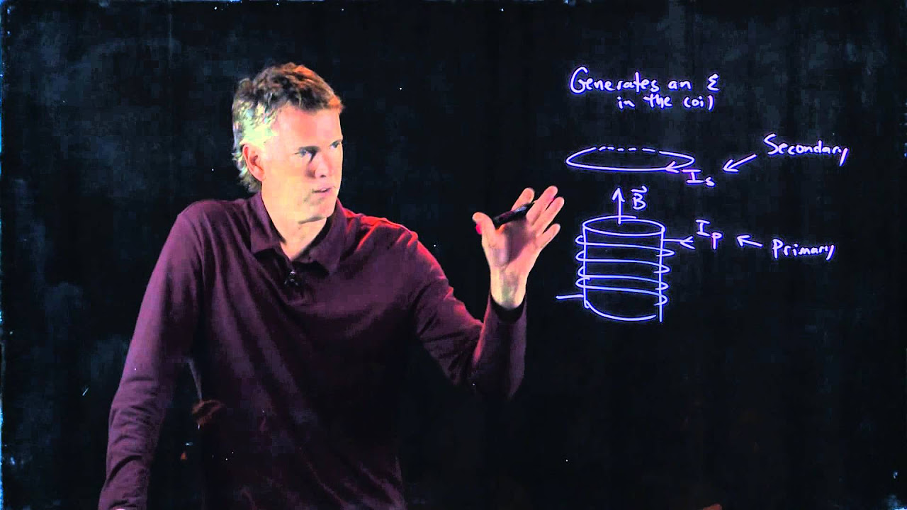
How does the transformer work and what are the relationships between its primary and secondary coils?
-A transformer consists of two coils, the primary and secondary, wound around a common iron core. The primary coil is connected to an AC supply, and the secondary coil is where the output is taken. The voltage and current in the secondary coil are determined by the ratio of the number of turns in the primary and secondary coils (V_secondary/V_primary = N_secondary/N_primary and I_secondary/I_primary = N_primary/N_secondary). Transformers can be step-up (increasing voltage) or step-down (decreasing voltage) depending on the number of turns in the coils.
Outlines
🧲 Faraday's Law of Electromagnetic Induction
This paragraph introduces Faraday's law of electromagnetic induction, explaining how a changing magnetic field induces an electric current in a coil of wire. It discusses the effects of moving a magnet into and out of a coil, the direction of the induced current, and the influence of the speed of the magnet's movement. The concept of magnetic flux, represented by the product of the magnetic field, area, and cosine of the angle between them, is introduced with the unit of measurement being the weber. The paragraph also highlights that the induced electromotive force (emf) and current depend on the rate of change of magnetic flux.
🔌 Electric Flux and Faraday's Law of Induction
The second paragraph delves deeper into electric flux, explaining how it is calculated and its relationship with the magnetic field and the area of the coil. It discusses the cases of the magnetic field being parallel or perpendicular to the coil's face and how these orientations affect the electric flux and induced emf. The paragraph also explains that increasing the number of coils in a system will increase the induced emf and current. The concept of Lenz's law is introduced, stating that the induced emf generates a current whose magnetic field opposes the change in flux.
👐 Right-Hand Rule and Lenz's Law Applications
This paragraph focuses on the practical application of the right-hand rule to determine the direction of the magnetic field and induced current. It uses examples of a bar magnet moving into and out of a coil, as well as a rectangular conductor moving into a magnetic field, to illustrate how Lenz's law dictates the direction of the induced current. The importance of understanding the relationship between the external magnetic field and the induced magnetic field is emphasized to predict the direction of the current correctly.
🔄 Direction of Induced Current in Changing Magnetic Fields
The fourth paragraph continues the discussion on the direction of induced current, using examples of a loop moving away from a magnetic field and a coil shrinking in size. It explains how the change in magnetic flux, whether due to motion or a change in area, affects the direction of the induced current. The paragraph reinforces the concept that the induced current always opposes the change in magnetic flux, as per Lenz's law.
🔗 Induced Current in Response to Changing Currents
This paragraph explores the relationship between changing currents in a wire and the induced current in a nearby circular wire. It uses the right-hand rule to determine the direction of the induced current when the current in a straight wire increases or decreases. The paragraph emphasizes that the induced current always opposes the change in flux, whether it is increasing or decreasing.
🔌 Circuit Analysis with Induced Current
The sixth paragraph presents a scenario involving a circular coil of wire with an internal coil and a battery, illustrating how the closing of a switch induces a current in the internal coil. It explains the concept of opposing the change in flux and how the induced current direction is determined based on the external magnetic field and Lenz's law.
⚡ Calculation of Induced EMF and Magnetic Flux
This paragraph provides a detailed mathematical approach to calculating the induced electromotive force (emf) and magnetic flux in various scenarios. It covers the change in magnetic field over time, the use of Faraday's law of induction, and the calculation of induced emf in a coil with multiple loops. The paragraph also discusses the calculation of resistance and power in a coil.
🌀 Induced EMF in a Moving Conductor
The eighth paragraph discusses the induced emf in a conductor moving in a magnetic field. It explains how the induced emf can be calculated using Faraday's law of induction and the relationship between the change in area exposed to the magnetic field and the velocity of the conductor. The paragraph also derives the formula for the induced emf in terms of the magnetic field, length of the conductor, and its velocity.
🔄 Induced EMF in a Rotating Coil
This paragraph introduces the concept of an alternating current (AC) generator, explaining how the induced emf in a rotating coil can be calculated. It discusses the relationship between the angular velocity, the strength of the magnetic field, and the area of the coil. The paragraph also calculates the maximum induced emf for a given generator setup.
🔌 Transformers and Their Function
The tenth paragraph discusses transformers, explaining their basic structure and function. It differentiates between step-up and step-down transformers and explains how the ratio of turns in the primary and secondary coils affects the voltage and current. The paragraph also covers the concept of power conservation in ideal transformers and provides formulas for calculating the voltage and current in both coils.
🔌 Transformer Calculations and Efficiency
The eleventh paragraph provides examples of calculating the voltage, current, and power in transformers. It explains how to determine the turns ratio and use it to find the secondary voltage and current based on the primary values. The paragraph also discusses the concept of transformer efficiency and how it can be calculated.
🌀 Inductance and Energy Storage in Inductors
This paragraph introduces inductance, explaining how it is calculated and its role in storing energy in the magnetic field of a coil. It discusses the potential energy stored in an inductor and how it can be calculated. The paragraph also covers the energy density of a magnetic field and provides a formula for calculating it.
🌀 Calculation of Inductance and Energy in Solenoids
The thirteenth paragraph provides a detailed example of calculating the inductance of a solenoid, the induced emf, and the potential energy stored in it. It explains how the inductance formula is derived and how it can be used to find the number of turns per meter and the length of the solenoid. The paragraph also calculates the magnetic field and energy density in the solenoid.
🌀 Energy Density and Magnetic Field Calculations
The final paragraph concludes the discussion by calculating the energy density and magnetic field in a solenoid with a given inductance, number of turns, and current. It reinforces the formulas for calculating these values and provides a comprehensive example to illustrate the process.
Mindmap
Keywords
💡Faraday's Law of Electromagnetic Induction
💡Magnetic Flux
💡Induced Current
💡Lenz's Law
💡Magnetic Field
💡Right-Hand Rule
💡Transformer
💡Inductance
💡Solenoid
💡Energy Density
Highlights
Faraday's Law of Electromagnetic Induction explains how a changing magnetic field induces an electric current in a coil.
The direction of induced current is determined by the counterclockwise direction when a magnet is moved into a coil.
The speed of the magnet's movement affects the magnitude of the induced current, with faster movements generating larger currents.
Inducing current can also occur by changing the coil's area or the angle between the coil and the magnetic field.
Magnetic flux is calculated using the formula: magnetic field times area times cosine of the angle, with units in webers.
The induced EMF is proportional to the rate of change of magnetic flux, impacting the induced current's strength.
Lenz's Law states that the induced EMF creates a current whose magnetic field opposes the change in magnetic flux.
The direction of induced current can be determined using the right-hand rule and considering the direction of the magnetic field.
The induced EMF can be calculated using the equation involving the number of coils, change in magnetic flux, and time.
Transformers operate on the principle of mutual induction, transferring electrical energy between primary and secondary coils.
Transformers can be step-up or step-down, adjusting voltage levels based on the ratio of turns in the primary and secondary coils.
The power transferred in an ideal transformer remains constant between the primary and secondary sides, assuming 100% efficiency.
Inductance measures the opposition to a change in current within a coil and is calculated using the formula involving the coil's dimensions and properties.
The potential energy stored in an inductor can be calculated using the formula involving inductance and the square of the current.
The energy density of a magnetic field can be determined using the formula relating to the magnetic field's strength and the permeability of free space.
Practical applications of transformers and inductors are discussed, including their role in adjusting voltage levels and storing energy.
The video concludes with a comprehensive overview of the principles and equations governing electromagnetic induction, transformers, and inductors.
Transcripts
Browse More Related Video
Faraday's Law of Electromagnetic Induction, Magnetic Flux & Induced EMF - Physics & Electromagnetism
michael faraday | law of electromagnetic induction | faraday's law of induction
Lenz's Law, Right Hand Rule, Induced Current, Electromagnetic Induction - Physics
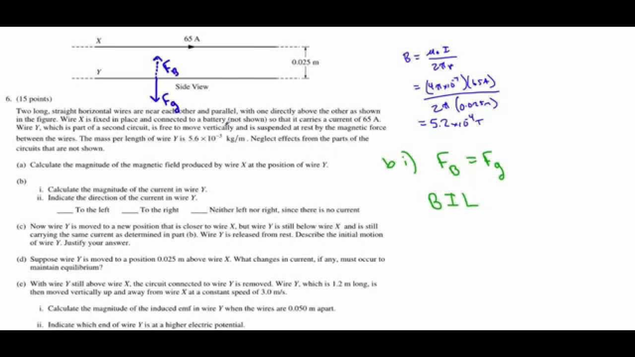
AP Physics B 2013 Question 6 - Electromagnetism
Magnetic Induction
Magnetic (AP Physics SuperCram Review)
5.0 / 5 (0 votes)
Thanks for rating: