Faraday's Law of Electromagnetic Induction, Magnetic Flux & Induced EMF - Physics & Electromagnetism
TLDRThis video script delves into Faraday's Law of Electromagnetic Induction, demonstrating how a changing magnetic field induces an electromotive force (emf) in a coil. It explains the formula for induced emf, which is proportional to the rate of change of magnetic flux. The script covers three methods to induce emf: altering the magnetic field, adjusting the coil's area, or changing the angle between the coil and the magnetic field. It concludes with a practical problem, calculating induced emf and current in a square coil with varying magnetic field, showcasing the power of electromagnetic induction.
Takeaways
- 🌐 Faraday's Law of Electromagnetic Induction is the focus, explaining how a changing magnetic field induces an electromotive force (emf) in a coil.
- 🔌 The setup involves an iron bar wrapped with coils connected to a voltmeter and a battery with a resistor to limit current flow.
- 💡 No induced current occurs in the second coil when the circuit's current is steady, but an induced current appears when the current changes, such as when a switch is closed.
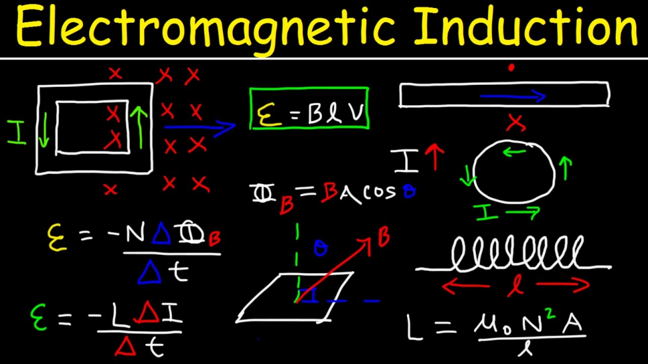
- 📉 The induced emf is calculated using the formula \( \text{Induced EMF} = -N \times \frac{\Delta \Phi}{\Delta t} \), where \( N \) is the number of turns, \( \Delta \Phi \) is the change in magnetic flux, and \( \Delta t \) is the change in time.
- 🧲 The magnetic flux is defined as the product of the magnetic field, the area of the coil, and the cosine of the angle between the field and the normal to the coil's face.
- 🔄 Three ways to induce an emf are by changing the magnetic field, altering the coil's area, or varying the angle between the magnetic field and the coil's normal line.
- 📊 The induced emf increases with the rate of change of magnetic flux, highlighting the importance of flux variation rather than its magnitude.
- 📚 An example problem demonstrates calculating induced emf and current in a square coil with a changing magnetic field, using the provided formula.
- 🔍 The example illustrates that the induced emf is negative, but for practical calculations, the magnitude is considered, yielding a current of 8 amps through a 20-ohm resistor.
- ⚡ The power dissipated by the resistor is calculated using \( P = I^2 \times R \), resulting in 1280 watts, showing the potential for significant energy generation from induced currents.
- 🔌 The number of coil loops affects the induced emf; more loops result in a greater induced emf, which is desirable for energy harvesting applications.
Q & A
What is the main focus of the video?
-The main focus of the video is Faraday's Law of electromagnetic induction.
What happens when a steady current flows in the first circuit with respect to the second coil?
-When a steady current flows in the first circuit, no electromotive force (emf) or current is induced in the second coil.
Why is an induced current generated in the second coil when the switch is closed?
-An induced current is generated in the second coil when the switch is closed because the current is changing, which changes the magnetic field and induces an emf in the second coil.
What does Faraday's Law of electromagnetic induction state?
-Faraday's Law of electromagnetic induction states that a change in magnetic field will give rise to an induced current in a circuit.
What is the equation associated with Faraday's Law of electromagnetic induction?
-The equation is: induced emf = -N * (change in magnetic flux / change in time), where N is the number of loops in the coil.
What are the three ways to induce an emf in a coil?
-The three ways to induce an emf in a coil are: changing the magnetic field, changing the area of the coil, and changing the angle between the magnetic field and the normal line of the coil.
How does moving a magnet into or out of a coil affect the magnetic flux?
-Moving a magnet into or out of a coil changes the magnetic field, which increases or decreases the magnetic flux and induces an emf in the coil.
What happens to the induced current if the magnet is held in place within the coil?
-If the magnet is held in place within the coil, no induced current flows because there is no change in magnetic flux.
How does changing the area of the coil affect the magnetic flux?
-Changing the area of the coil (by stretching or compressing it) changes the magnetic flux, which induces an emf in the coil.
What is the effect of changing the angle between the magnetic field and the normal line of the coil?
-Changing the angle between the magnetic field and the normal line of the coil changes the magnetic flux, which induces an emf in the coil.
How is the induced emf calculated in the practice problem provided?
-The induced emf is calculated using the formula: induced emf = -N * (change in magnetic flux / change in time). In the practice problem, N is 50, the change in magnetic field is from -3 to 5 Tesla, the area of the coil is 0.04 m², the angle is 0 degrees, and the change in time is 0.1 seconds.
What is the current flowing through the resistor in the practice problem?
-The current flowing through the resistor is calculated as the induced emf divided by the resistance. In the practice problem, the induced emf is 160 volts and the resistance is 20 ohms, resulting in a current of 8 amps.
How is the power dissipated by the resistor calculated?
-The power dissipated by the resistor is calculated using the formula: power = current² * resistance. In the practice problem, the current is 8 amps and the resistance is 20 ohms, resulting in a power dissipation of 1280 watts.
How does the number of loops in the coil affect the induced emf?
-The number of loops in the coil directly affects the induced emf; increasing the number of loops increases the induced emf. For example, with 50 loops, the induced emf is 160 volts, whereas with a single loop, it would only be 3.2 volts.
Outlines
🌐 Faraday's Law of Electromagnetic Induction
This paragraph introduces Faraday's law of electromagnetic induction, demonstrating how an induced electromotive force (emf) is generated when there is a change in the magnetic field. The setup involves an iron bar wrapped with wire coils, connected to a voltmeter and a battery through a switch and a resistor. When the switch is closed, inducing a current in the circuit, the change in magnetic field induces an emf in the second coil. The formula for induced emf is given as \(\mathcal{E} = -N \frac{\Delta \Phi}{\Delta t}\), where \(\mathcal{E}\) is the induced emf, \(N\) is the number of turns in the coil, \(\Delta \Phi\) is the change in magnetic flux, and \(\Delta t\) is the change in time. The paragraph also explains three ways to induce an emf: changing the magnetic field, changing the area of the coil, or changing the angle between the magnetic field and the normal line of the coil.
🔌 Calculating Induced EMF and Current
This paragraph delves into the calculation of induced emf and current in a circuit with a square coil of wire. The coil has 50 loops and is subjected to a magnetic field that changes from -3 Tesla to 5 Tesla. The formula for induced emf is applied, focusing on the change in magnetic field (\(\Delta B\)), the area of the coil (\(A\)), and the angle (\(\theta\)). The calculation shows that the induced emf is -160 volts, which is then used to determine the current flowing through a 20-ohm resistor (8 amps). The power dissipated by the resistor is also calculated using the formula \(P = I^2R\), resulting in 1280 watts. The paragraph emphasizes the importance of the number of loops in increasing the induced emf.
🔗 Power Dissipation in Electromagnetic Induction
The final paragraph discusses the power dissipated by a resistor in an electromagnetic induction setup. It explains that the power can be significant when there is a change in the magnetic field or flux in the coil. The induced emf is calculated without considering the negative sign, and the current is determined by dividing the induced emf by the resistance. The example provided shows that with a 160-volt induced emf and a 20-ohm resistor, the current is 8 amps. The power dissipated by the resistor is then calculated as 1280 watts, highlighting the potential for generating substantial power through changes in magnetic fields and flux.
Mindmap
Keywords
💡Faraday's Law of Electromagnetic Induction
💡Induced Current
💡Electromotive Force (emf)
💡Magnetic Flux
💡Magnetic Field
💡Coil
💡Resistor
💡Voltmeter
💡Theta (θ)
💡Power Dissipated
💡Practice Problem
Highlights
Faraday's law of electromagnetic induction is the focus of the video.
Demonstration of electromagnetic induction using an iron bar, wire coils, a voltmeter, and a battery.
Explanation of why no current is induced in the second coil when the current is steady.
Induced current occurs when the current in the circuit changes, illustrating Faraday's law.
The formula for Faraday's law of electromagnetic induction is introduced.
The relationship between the rate of flux change and the induced EMF is explained.
Magnetic flux is defined as the product of the magnetic field, area, and cosine of the angle theta.
Three methods to induce an EMF are discussed: changing the magnetic field, area of the coil, or the angle.
Practical example of inducing EMF by moving a magnet into a coil.
The impact of a constant magnetic field on the induction of current when the magnet is stationary.
Demonstration of inducing EMF by changing the area of a circular coil.
Explanation of how changing the angle between the magnetic field and the coil induces EMF.
Introduction to a practice problem involving a square coil and a changing magnetic field.
Calculation of the induced EMF in a coil with a given magnetic field change and area.
Determination of the current flowing through a resistor connected to the coil.
Calculation of power dissipated by the resistor due to the induced current.
The significance of the number of coil loops in the magnitude of the induced EMF.
Transcripts
Browse More Related Video
Faradays Law in 3 minutes
Faraday's & Lenz's Law of Electromagnetic Induction, Induced EMF, Magnetic Flux, Transformers
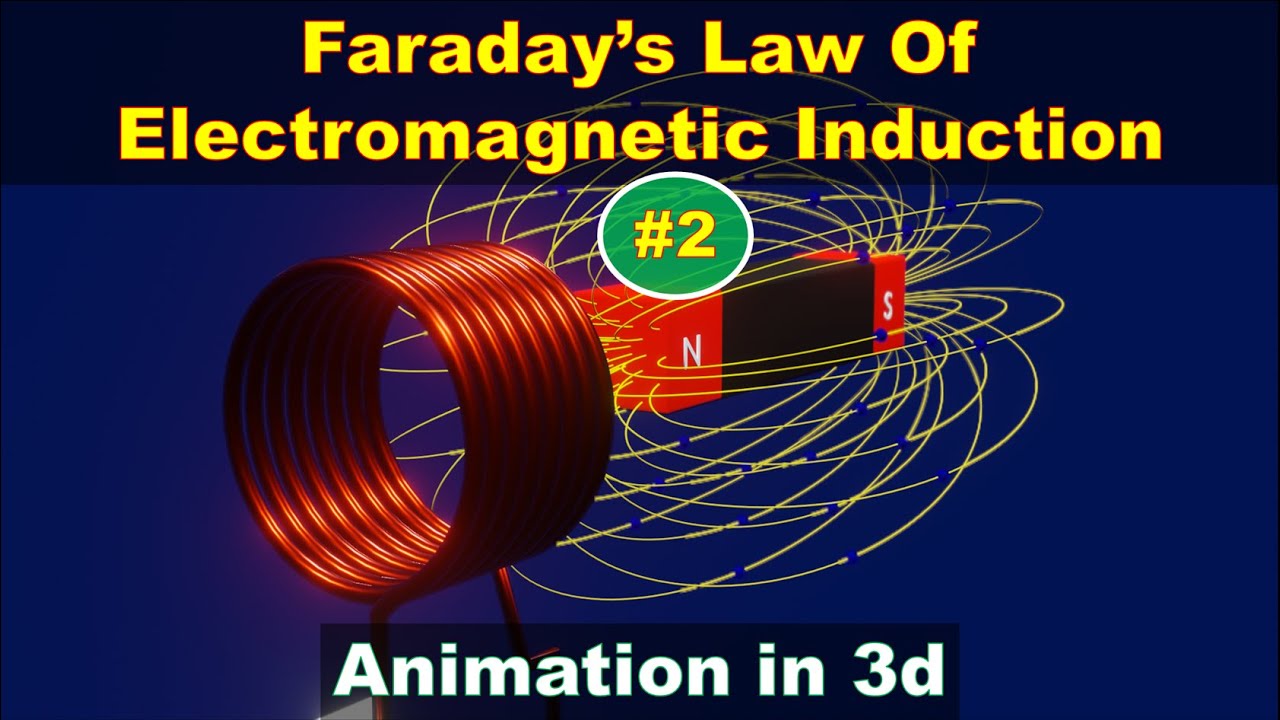
michael faraday | law of electromagnetic induction | faraday's law of induction

10. Ampere's Law
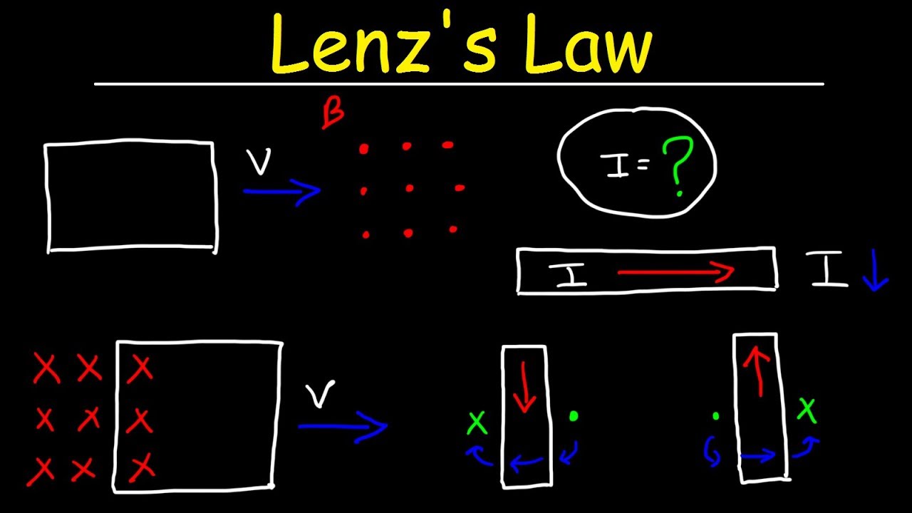
Lenz's Law, Right Hand Rule, Induced Current, Electromagnetic Induction - Physics
AP Physics B 2013 Question 6 - Electromagnetism
5.0 / 5 (0 votes)
Thanks for rating: