EMF and flux explained
TLDRThis video script elucidates the concept of magnetic flux and its role in generating electromotive force (EMF) as described by Faraday's law. The analogy of rain and a loop helps visualize how magnetic field strength and loop area affect flux. The script further explains how the rotation of the loop leads to a sinusoidal change in flux, crucial for understanding the relationship between flux variation and the induced EMF. The law is demonstrated with graphs, highlighting the phase difference between flux and EMF, and the significance of Lenz's law in the direction of the induced EMF.
Takeaways
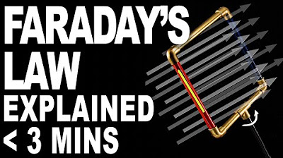
- 🌧️ The concept of flux is introduced using the analogy of rain, where raindrops represent magnetic field lines passing through a loop.
- 🔍 Flux is determined by two factors: the strength of the magnetic field (like the intensity of rain) and the area of the loop (size of the container catching the rain).
- 📏 Magnetic flux is the product of magnetic flux density and the area of the loop perpendicular to the field lines.
- 📐 The angle of the loop relative to the magnetic field affects the amount of flux captured, similar to how the angle affects the amount of rain captured.
- 🔄 A changing flux can induce an electromotive force (EMF), which is the core of Faraday's law of electromagnetic induction.
- 📉 The EMF is proportional to the rate of change of flux, not the flux itself, emphasizing the importance of the change rather than the state.
- 📈 The relationship between flux and EMF is sinusoidal, with the EMF starting at zero, reaching a maximum, and returning to zero as the loop rotates.
- 🔁 Faraday's law states that EMF is equal to the negative rate of change of flux, indicating the direction of induced current due to Lenz's law.
- 🔌 The negative sign in Faraday's law accounts for the direction of the induced EMF, which opposes the change that produced it.
- 🔄 As the loop rotates, the flux changes, leading to an alternating EMF, which is the basis for alternating current (AC).
- 🤓 The explanation aims to clarify the often misunderstood concept of flux and its role in generating EMF, providing a visual and tangible analogy for better understanding.
Q & A
What is the main concept discussed in the video?
-The main concept discussed in the video is the concept of flux and how changing flux can lead to the generation of an electromotive force (EMF), which is essentially an explanation of Faraday's law.
What is flux, and why do students often struggle to understand it?
-Flux is a measure of how much magnetic field lines pass through a given area. Students often struggle to understand it because it involves abstract concepts like magnetic field lines and their interaction with physical objects like loops.
How does the video use the analogy of rain to explain flux?
-The video uses the analogy of rain falling as magnetic field lines and a loop to represent the area capturing these lines. The amount of rain (magnetic field lines) captured is determined by the strength of the rain (magnetic field strength) and the size of the loop (area).
What are the two factors that determine the amount of magnetic field lines captured by a loop according to the video?
-The two factors are the strength of the magnetic field (represented by the heaviness of the rain) and the area of the loop (the size of the loop used to capture the rain).
How does the orientation of the loop affect the amount of flux captured?
-The orientation of the loop affects the amount of flux captured because it changes the effective area that can capture the magnetic field lines. If the loop is perpendicular to the field lines, it captures the maximum flux; if parallel, it captures none.
What does Faraday's law state about the relationship between EMF and flux?
-Faraday's law states that the EMF induced in a circuit is proportional to the rate of change of magnetic flux through the circuit.
Why is the EMF at a maximum when the flux is at zero in the video's explanation?
-The EMF is at a maximum when the flux is at zero because that is the point of maximum change from zero flux to some positive flux, indicating a rapid change in flux, which is what induces the maximum EMF according to Faraday's law.
What is the significance of the negative sign in Faraday's law as mentioned in the video?
-The negative sign in Faraday's law indicates the direction of the induced EMF is opposite to the direction of the change in flux, which is a result of Lenz's law stating that the induced EMF will always act to oppose the change that produced it.
How does the video demonstrate the relationship between the change in flux and the induced EMF?
-The video demonstrates this by showing a sinusoidal graph of flux and its corresponding derivative graph, which represents the induced EMF. The EMF graph is 90 degrees out of phase with the flux graph, showing that the EMF is at a maximum when the flux is changing most rapidly.
What does the video conclude about the EMF produced as the loop rotates in a magnetic field?
-The video concludes that as the loop rotates in a magnetic field, it produces an alternating EMF due to the continuous change in flux, resulting in a sinusoidal pattern of EMF that changes every 180 degrees of rotation.
Outlines
🌧️ Understanding Flux and EMF with Rain Analogy
This paragraph introduces the concept of magnetic flux, using a rain analogy to explain how flux is determined by the strength of the magnetic field (rain intensity) and the area of the loop (size of the container). It explains that flux is the product of magnetic flux density and the area perpendicular to the field lines. The analogy also clarifies how the angle of the loop affects the amount of 'rain' (magnetic field lines) captured, illustrating the concept of flux linkage. The paragraph further discusses how a changing flux can induce an electromotive force (EMF), as described by Faraday's law, and uses a sinusoidal graph to demonstrate the relationship between flux and EMF, emphasizing the maximum and minimum rates of change at different positions of the loop.
🔁 Generating Alternating EMF Through Flux Variation
The second paragraph builds on the previous explanation to describe the process of generating an alternating EMF as the loop rotates and the flux changes. It emphasizes that the EMF is produced as the loop moves through different positions, resulting in a sinusoidal pattern of EMF that is 90 degrees out of phase with the flux curve. The explanation highlights the negative sign in Faraday's law, which is attributed to Lenz's law, indicating that the direction of the induced EMF opposes the change in flux. The paragraph concludes by reinforcing the idea that even when the flux is zero, the rate of change of flux—and thus the induced EMF—can be at a maximum or minimum, depending on the rotational position of the loop.
Mindmap
Keywords
💡Flux
💡Faraday's Law
💡Magnetic Field Lines
💡Electromotive Force (EMF)
💡Magnetic Flux Density
💡Area
💡Rate of Change
💡Lenz's Law
💡Sinusoidal Curve
💡Alternating Current (AC)
Highlights
The video aims to explain the concept of flux and its relation to EMF, focusing on Faraday's law.
Flux is described using an analogy of rain, where the rain represents magnetic field lines.
The amount of rain captured by a loop is determined by the rain's intensity and the loop's area.
Magnetic flux density is compared to the intensity of rain, influencing the amount of magnetic field lines captured.
The area of the loop is crucial in determining the magnetic flux, as it affects how many field lines are captured.
Flux is calculated as the product of magnetic flux density and the area of the loop.
Changing the loop's orientation affects the amount of flux captured, with certain angles resulting in zero flux.
The relationship between the loop's orientation and flux is explained using a trigonometric ratio.
A changing flux can induce an EMF, as demonstrated by rotating the loop in a magnetic field.
Faraday's law states that EMF is proportional to the rate of change of flux, not the flux itself.
The video illustrates the sinusoidal pattern of flux and EMF as the loop rotates in a magnetic field.
The phase difference between the flux and EMF curves is highlighted, showing a 90-degree shift.
Lenz's law is introduced, explaining the negative sign in Faraday's law relating to the direction of EMF.
The video demonstrates how the loop's rotation results in an alternating EMF as it changes direction every 180 degrees.
The practical application of this concept is shown in generating alternating current through the rotation of the loop.
The video concludes by hoping that the explanation makes sense of the relationship between flux and EMF.
Transcripts
Browse More Related Video

Faradays Law in 3 minutes

Lenz's Law, Right Hand Rule, Induced Current, Electromagnetic Induction - Physics

10. Ampere's Law

Faraday's Law of Electromagnetic Induction, Magnetic Flux & Induced EMF - Physics & Electromagnetism

michael faraday | law of electromagnetic induction | faraday's law of induction

EMF & flux equation (& graph) of AC generator | Electromagnetic induction | Physics | Khan Academy
5.0 / 5 (0 votes)
Thanks for rating: