Drawing Free-Body Diagrams EXPLAINED with Examples
TLDRIn this educational video, Mark from Ace Tutors introduces free body diagrams, a fundamental tool in physics for visualizing external forces on an object. He outlines a simple four-step process to draw these diagrams, using examples like a box on a ramp and a pulley system. The steps include simplifying the object, identifying and drawing force vectors, labeling them, and establishing a coordinate system for organization. Mark emphasizes the importance of consistency and practice to master this skill.
Takeaways
- 📚 A free body diagram is a fundamental tool in physics used to visualize an object and all the external forces acting on it.
- 🎨 The first step in drawing a free body diagram is to represent the object of interest as a simplified free body, such as a square for a box.
- 📐 The second step involves drawing vectors for each force applied to the object, starting from where the force acts and pointing in the direction it is applied.
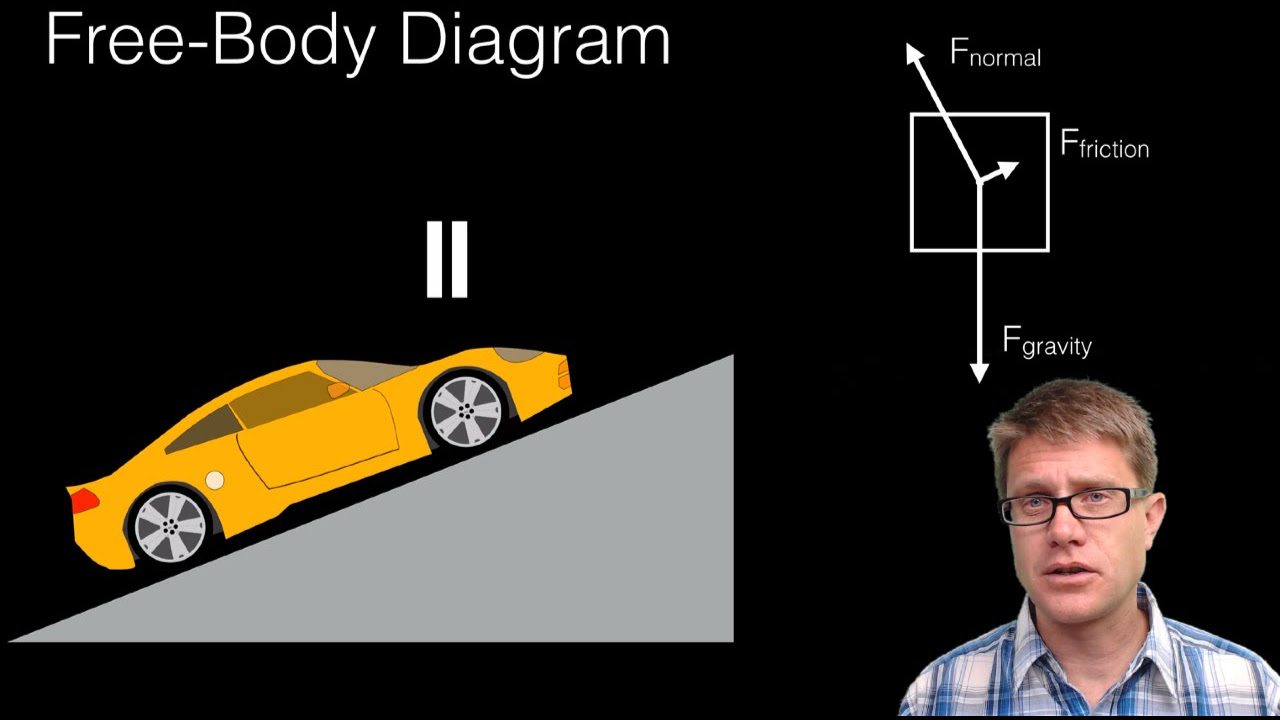
- 🔽 The weight of the object is a downward force acting from its center of gravity and is one of the primary vectors to include.
- ↕ The normal force is an upward force exerted by the ramp on the object, perpendicular to the surface.
- 🚫 Friction is another force to consider, acting up the ramp and preventing the object from sliding down.
- 📝 It's helpful but not always necessary to draw the size of vectors relative to each other to indicate their magnitudes.
- 🏷️ Labeling each force vector with a unique identifier, such as 'w' for weight, 'f_n' for normal force, and 'f_f' for friction, helps avoid confusion.
- 📊 The final step is to draw a coordinate system to maintain consistency and organization, which can be oriented traditionally or aligned with the forces' angles.
- 🔄 Practice is key to becoming proficient with free body diagrams, as demonstrated through the example of a pulley system.
- 👍 Encouragement to like and subscribe for more educational content on physics and problem-solving.
Q & A
What is the main purpose of a free body diagram in physics?
-A free body diagram is used to visualize an object and all of the external forces applied to it, which helps in analyzing the physical situation and solving related problems.
What are the four steps to draw a free body diagram according to the video?
-The four steps are: 1) Draw a simplified version of the object as a free body, 2) Draw vectors for each force applied to the object, starting from where the force acts, 3) Label each force vector uniquely, and 4) Draw a coordinate system to stay organized and consistent.
Why is it important to draw a simplified version of the object in the first step?
-Drawing a simplified version helps to focus on the object of interest without the distraction of other surfaces, objects, or forces that might be interacting with it.
What is the role of vectors in a free body diagram?
-Vectors represent the forces applied to the object, showing both the magnitude and direction of each force, starting from the point where the force is acting.
Why might it be helpful to draw the size of the vectors relative to one another?
-Drawing the size of the vectors relative to one another can help in visualizing the relative magnitudes of the forces, although it's not always necessary as force magnitudes might not be known initially.
Outlines
📚 Introduction to Free Body Diagrams
Mark from Ace Tutors introduces free body diagrams as a fundamental tool in physics for visualizing an object and the external forces acting upon it. He outlines a four-step process to draw these diagrams, starting with an example of a box on a 30-degree ramp. The explanation emphasizes the importance of understanding the basic concept before applying it to various problems.
🎯 Steps to Draw a Free Body Diagram
The video script details a four-step method for drawing free body diagrams. First, simplify the object of interest as a free body, ignoring other surfaces or forces. Second, draw vectors for each force applied to the object, starting from the point of action and pointing in the direction of the force. Third, label each vector uniquely to avoid confusion during calculations. Lastly, draw a coordinate system to maintain consistency and organization throughout the problem-solving process. The script provides guidance on choosing an appropriate orientation for the coordinate system based on the object and forces involved.
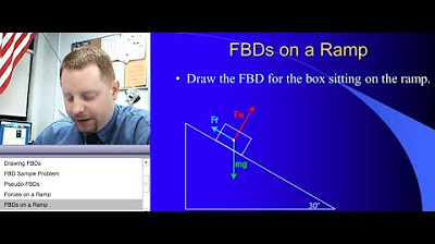
📝 Example: Free Body Diagram of a Box on a Ramp
An example is given to demonstrate the steps for drawing a free body diagram of a box sitting motionless on a 30-degree ramp. The process includes drawing the box as a simple square, identifying and drawing the vectors for the weight, normal force, and friction, and labeling them accordingly. The script also discusses the option of drawing vector magnitudes relative to each other and the importance of a consistent coordinate system, suggesting traditional or ramp-aligned coordinates based on the problem's context.
🔄 Additional Example: Pulley System Free Body Diagram
A second example illustrates the application of the four-step process to a pulley system, where a weightless wheel is subjected to tension from a cable and the weight of another block. The summary explains how to represent the forces due to the block and the cable with vectors, label them, and choose an appropriate coordinate system that aligns with the vertical forces involved in the system.
Mindmap
Keywords
💡Free Body Diagrams
💡Simplified Object
💡Vectors
💡Center of Gravity
💡Normal Force
💡Friction
💡Labeling
💡Coordinate System
💡Consistency
💡Pulley System
💡Tension
Highlights
Mark from Ace Tutors introduces free body diagrams, a fundamental tool in physics.
Free body diagrams are used to visualize an object and the external forces applied to it.
A four-step process is presented for drawing free body diagrams.
The first step is to draw a simplified version of the object of interest as a free body.
The second step involves drawing vectors for each force applied to the object.
Force vectors should start from where the force is acting and point in the direction of application.
The weight of the object acts from its center of gravity and pulls straight downward.
The normal force is the ramp pushing back up on the object, perpendicular to the surface.
Friction force acts up the ramp, opposing motion and keeping the object stationary.
Drawing the size of vectors relative to each other can be helpful but isn't always necessary.
Labeling each force vector uniquely prevents confusion during calculations.
The final step is to draw a coordinate system to maintain consistency and organization.
The orientation of the coordinate system should make sense for the object and applied forces.
An example of a pulley system is used to demonstrate the application of the four steps.
In the pulley system example, the weight of a block is replaced with a downward force vector.
The force due to the tension in the cable is represented by vectors labeled with 't'.
A vertical coordinate system is chosen for the pulley system example for simplicity.
Following these steps and practicing will enable one to become proficient in drawing free body diagrams.
The video encourages viewers to like and subscribe for more educational content.
The video concludes with a motivational message about pursuing big dreams despite academic challenges.
Transcripts


5.0 / 5 (0 votes)
Thanks for rating: