How Combinational Logic Devices Work - The Learning Circuit
TLDRIn this episode of 'The Learning Circuit' by element14, the focus is on combinational logic devices, which are more intricate than individual logic gates. The video explains how combinational logic outputs depend solely on the current state of inputs, unlike sequential logic which also considers past states. It delves into common combinational devices such as multiplexers, demultiplexers, encoders, and decoders. Multiplexers act as digital switches, directing inputs based on select and enable pins. Demultiplexers function in reverse, distributing a single input to multiple outputs. Encoders convert input data into binary codes, with priority encoders resolving issues of overlapping inputs. Decoders, on the other hand, translate binary data into other forms, like BCD for controlling seven-segment displays or decimal for base-10 counting. The video simplifies complex concepts, making them accessible for those eager to learn about digital logic.
Takeaways
- 🌐 The video is part of a series on digital logic, focusing on combinational logic devices, which are more complex than individual logic gates.
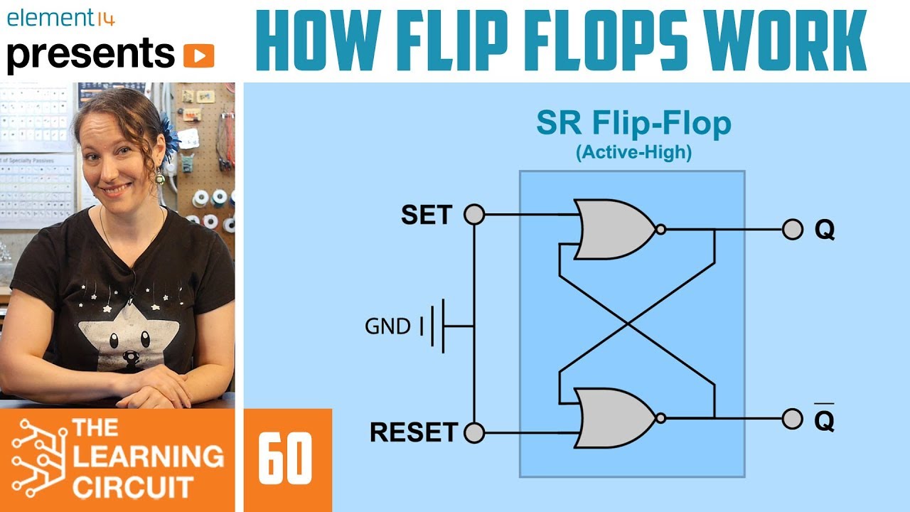
- 🔄 Combinational logic devices differ from sequential logic in that the output of the former depends only on the current state of inputs, while the latter also considers previous states and has memory.
- 🔌 Multiplexers (MUX) are digital switches that select one of many inputs to send to a single output, controlled by select and enable pins.
- 🔠 Demultiplexers (DEMUX) function in reverse to MUXs, taking a single input and distributing it to one of many outputs based on selector pins.
- 🔢 Encoders convert data at their inputs into a binary code representing a number, with priority encoders assigning a hierarchy to inputs to avoid conflicts.
- 📊 Decoders take binary data and translate it into other forms, such as decimal or signals to control displays like seven-segment displays.
- 🔑 The 74LS157 is a 4-channel, 2-to-1 data selector MUX with select and enable pins determining the output for each channel.
- 🔄 The enable pin (pin 15) on a MUX can either enable the output (when low) or disable it (when high), with disabled meaning all outputs go low.
- 🔢 Binary encoders output binary numbers based on the active low input, representing numbers from 0 to 3 depending on which input is active.
- 🔢 BCD to seven-segment decoders translate four-digit binary coded decimal (BCD) inputs into seven outputs that control the segments of a display to show numbers.
- 📈 Encoders have more inputs than outputs, while decoders have more outputs than inputs, similar to zipping and unzipping files, respectively.
Q & A
What is the main difference between combinational logic and sequential logic?
-The main difference is that in combinational logic, the output is solely a product of the current states of the inputs, whereas in sequential logic, the output is dependent on both the current and previous states of the inputs, meaning sequential logic has memory.
What is a multiplexer and what does it do?
-A multiplexer, sometimes called a data selector or mux, acts as a digitally controlled switch. It takes multiple inputs and routes them to a single output based on the state of select and enable pins.
Can you explain how the select and enable pins work in a 4-channel 2-to-1 data selector multiplexer?
-In a 4-channel 2-to-1 data selector multiplexer, the select pin (pin 1) determines whether input A or B is selected for each channel (A when high, B when low). The enable pin (pin 15) controls whether the output is enabled (low) or disabled (high), with all outputs going low when disabled.
What is the function of a demultiplexer and how does it differ from a multiplexer?
-A demultiplexer, or demux, works in reverse to a multiplexer. While a multiplexer takes multiple inputs and routes them to a single output, a demultiplexer takes a single input and routes it to multiple outputs based on the state of the selector pins.
How are encoders different from decoders in terms of their functionality?
-Encoders take data at their inputs, determine the number it represents, and output that data as a binary code. Decoders, on the other hand, take binary data and translate it into other forms of data, such as decimal or signals to control displays.
What is a priority encoder and how does it solve the issue of overlapping active inputs in a standard binary encoder?
-A priority encoder assigns a priority level to each input pin, from highest to lowest. It ensures that if multiple inputs are active, only the input with the highest priority is considered for the output, thus avoiding the issue of overlapping active inputs that can occur in standard binary encoders.
How does a BCD to seven-segment decoder work?
-A BCD to seven-segment decoder takes four inputs of binary-coded decimal (BCD) data and translates it into seven outputs that control the segments of a seven-segment display, allowing it to show numbers in a human-readable format.
What is the significance of the term '2 to the N' in the context of multiplexers and demultiplexers?
-The term '2 to the N' refers to the number of inputs that a multiplexer or demultiplexer can handle, where N is the number of select lines. For example, a 2 to the first (2^1) is a 2-to-1 MUX or a 1-to-2 DMUX, each having one selector line.
Can you provide an example of how a BCD to decimal decoder is used?
-A BCD to decimal decoder is used to convert binary-coded decimal data into a form that can control ten outputs, one for each numeral from zero to nine. This is useful in applications where you need to represent decimal numbers directly, such as in digital clocks or displays.
What is the analogy used in the script to help understand the difference between encoders and decoders?
-The script uses the analogy of zip files to explain the difference: encoders take data and make it smaller, like zipping a file, while decoders take data and make it bigger, like unzipping a file.
Outlines
🔌 Introduction to Combinational Logic Devices
The script introduces the topic of digital logic, specifically focusing on combinational logic devices. It contrasts combinational logic with sequential logic, highlighting that the former's output depends solely on the current state of inputs, while the latter also considers past states, indicating memory. The most common combinational logic devices discussed are multiplexers, demultiplexers, encoders, and decoders. Multiplexers are described as digital switches that select one of several inputs to produce an output, with details on a 4-channel 2-to-1 data selector multiplexer, including its pin functions and logic diagram. Demultiplexers are mentioned as the reverse operation of multiplexers, taking a single input and distributing it to multiple outputs.
🔄 Functions and Applications of Encoders and Decoders
This paragraph delves into the functionality of encoders and decoders in digital logic systems. Encoders are explained as devices that convert input data into binary code, with an emphasis on priority encoders that assign a priority level to each input to avoid conflicts when multiple inputs are active. The script also touches on binary encoders and their use in applications like keyboards, robot arms, and microprocessor interrupt detection. Decoders are presented as the counterparts to encoders, translating binary data into other formats, such as decimal or controlling seven-segment displays. The explanation includes how BCD (Binary Coded Decimal) differs from standard binary and how BCD-to-seven-segment decoders work to display numbers. The analogy of encoders 'zipping' data (making it smaller) and decoders 'unzipping' it (making it larger) is used to clarify their roles.
📚 Conclusion and Invitation to the Element14 Community
The final paragraph wraps up the video script by summarizing the discussion on combinational logic devices and inviting viewers to engage further with the topic. It encourages viewers to ask questions or share insights related to multiplexers, demultiplexers, encoders, and decoders on the Element14 community platform. The script ends on a positive note, promoting continued learning and engagement with the subject matter, and is concluded with a musical sign-off.
Mindmap
Keywords
💡Digital Logic
💡Combinational Logic
💡Sequential Logic
💡Multiplexer (MUX)
💡Demultiplexer (DEMUX)
💡Encoder
💡Decoder
💡Binary Code
💡Seven-Segment Display
💡BCD (Binary-Coded Decimal)
💡Element14 Community
Highlights
Introduction to digital logic and combinational logic devices.
Difference between combinational and sequential logic, with combinational logic lacking memory.
Explanation of multiplexers (MUX) as digitally controlled switches.
Description of a 4-channel 2-to-1 data selector multiplexer and its pin functions.
How select and enable pins affect the output of a multiplexer.
Example of selecting inputs A or B based on the state of select pin 1.
Behavior of the enable pin 15 in enabling or disabling the output.
Logic diagram explanation of the 2-to-1 multiplexer.
Introduction to 4-to-1 and 8-to-1 multiplexers and their selector pins.
Function of demultiplexers (DEMUX) as the reverse of multiplexers.
Explanation of 2-to-the-N devices, where N equals the number of select lines.
Operation of a one-to-eight active low demultiplexer with selector pins.
Role of encoders and decoders in translating data forms.
Working of binary encoders and the issue of input combination conflicts.
Solution to input conflicts using priority encoders with input priority levels.
Function of binary decoders in translating binary to other data forms like decimal.
Application of BCD to seven-segment decoders for controlling LED lit segments.
Explanation of BCD and its difference from standard binary counting.
Use of BCD to seven-segment decoders in displaying numbers on LED displays.
Comparison of encoders and decoders in terms of inputs and outputs, like zipping and unzipping files.
Invitation to the element14 community for further discussion on combinational logic devices.
Transcripts


5.0 / 5 (0 votes)
Thanks for rating: