High School Physics - Series Circuits
TLDRIn this informative video, Mr. Fullerton explains the fundamentals of series circuits, focusing on key concepts such as Kirchhoff's laws, Ohm's law, and the use of voltage, current, resistance, and power tables for circuit analysis. He demonstrates how to calculate equivalent resistance and power dissipation in series circuits, using several practical examples to illustrate the process. The video is an excellent resource for anyone seeking to understand and analyze series circuits effectively.
Takeaways
- 🔋 A series circuit has a single current path and is characterized by a complete closed loop.
- 💡 Kirchhoff's Current Law (KCL) states that the sum of currents entering any part of a circuit equals the sum of currents leaving that part.
- 🔄 Kirchhoff's Voltage Law (KVL) asserts that the sum of potential drops around any closed loop in a circuit must equal zero.
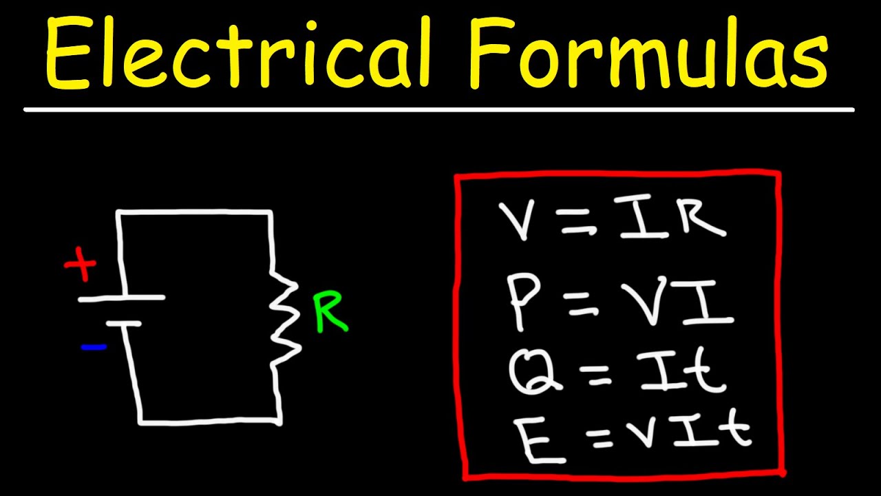
- 📐 Ohm's Law is used to calculate voltage drop across resistors in a series circuit: V = I * R.
- 🔌 The current throughout a series circuit is constant, meaning it is the same at any point in the circuit.
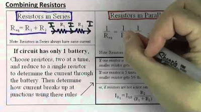
- 🔧 Equivalent resistance in a series circuit is the sum of the individual resistances: R_total = R1 + R2 + ... + Rn.
- 🔦 The ammeter reads the total current flowing through the circuit in a series configuration.
- 📊 A verb table is a useful tool for circuit analysis, listing circuit elements and their corresponding voltage, current, resistance, and power.
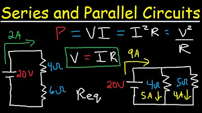
- 🔆 Power in a series circuit can be calculated using the formulas: P = IV, P = I^2R, or P = V^2/R.
- 🔍 To find the unknown resistance in a series circuit, use the known current and voltage values along with Ohm's Law.
- ⚡ The total power used in a series circuit is the sum of the power used in each individual resistor: P_total = P1 + P2 + ... + Pn.
Q & A
What is a series circuit?
-A series circuit is a type of electrical circuit where all the components are connected one after the other in a single path, allowing only one current path for the flow of charge.
What is the main characteristic of current in a series circuit?
-In a series circuit, the current is constant throughout the circuit. This means that the same current flows through every component in the series, regardless of the resistance values.
What are Kirchhoff's Current Law (KCL) and Kirchhoff's Voltage Law (KVL)?
-Kirchhoff's Current Law states that the sum of all currents entering any junction in a circuit is equal to the sum of all currents leaving that junction. Kirchhoff's Voltage Law states that the sum of all potential differences (voltages) around any closed loop in a circuit must equal zero.
How can Ohm's Law be used to calculate the potential difference across a resistor in a series circuit?
-Ohm's Law, which states that V = I * R, can be used to calculate the potential difference (voltage) across a resistor by knowing the current flowing through it and its resistance value. Multiplying the current (I) by the resistance (R) will give you the voltage (V) across that resistor.
What is the formula for calculating the equivalent resistance of resistors connected in series?
-The equivalent resistance (R_eq) of resistors connected in series is simply the sum of the individual resistances. That is, R_eq = R1 + R2 + R3 + ... + Rn, where R1, R2, R3, etc., are the resistance values of the individual resistors.
How can a verb table be used to analyze a series circuit?
-A verb table is a useful tool for analyzing circuits, where 'V' stands for voltage, 'I' for current, 'R' for resistance, and 'P' for power. The table lists all circuit elements on the left side and standard units (volts, amps, ohms, watts) as the headers for columns. By filling in known values and using circuit formulas like Ohm's law and power equations, the table helps determine unknown values for each element in the circuit.
In the example with three 2 kiloohm resistors in series, what is the equivalent resistance?
-For three 2 kiloohm (2000 ohm) resistors connected in series, the equivalent resistance is the sum of the individual resistances, which is 2000 ohms + 2000 ohms + 2000 ohms, equaling 6000 ohms or 6 kiloohms.
What is the total power used by a series circuit with a 12-volt source and three 2 kiloohm resistors?
-The total power used by the circuit can be calculated using the power formula P = V^2 / R, where V is the total voltage and R is the equivalent resistance. With a 12-volt source and an equivalent resistance of 6000 ohms, the total power is P = 12^2 / 6000 = 0.0024 watts or 2.4 milliwatts.
How can you find the current flowing through a 4 ohm resistor if a 2 ohm resistor in series with it has a current of 2 amps?
-Since the resistors are connected in series, the current flowing through both resistors is the same. Therefore, if the current through the 2 ohm resistor is 2 amps, the current through the 4 ohm resistor is also 2 amps.
What is the total power dissipated by two 4-ohm resistors each in a series circuit connected to a 16-volt battery?
-The total power can be calculated using the formula P = V * I, where V is the total voltage and I is the current. The total resistance is 8 ohms (4 ohms + 4 ohms), and with a 16-volt source, the current is I = V / R = 16V / 8 ohms = 2 amps. Thus, the total power is P = 16V * 2A = 32 watts.
In a series circuit with a 50-ohm resistor and an unknown resistor R connected to a 120-volt source, and an ammeter reading of 0.5 amp, what is the value of resistor R?
-Using Ohm's Law for the total circuit (V = I * R_total), and knowing the total voltage (V = 120V) and the total current (I = 0.5A), we can find the total resistance (R_total = V / I = 120V / 0.5A = 240 ohms). Since one resistor is 50 ohms, the unknown resistor R must be R_total - R1 = 240 ohms - 50 ohms = 190 ohms.
What is the power dissipated by the 50-ohm resistor in the previous question?
-The power dissipated by a resistor can be calculated using the formula P = I^2 * R. With a current of 0.5 amp and a resistance of 50 ohms, the power dissipated by the 50-ohm resistor is P = (0.5A)^2 * 50 ohms = 0.25A^2 * 50 ohms = 12.5 watts.
Outlines
🔌 Introduction to Series Circuits and Kirchhoff's Laws
This paragraph introduces the concept of series circuits, emphasizing that they contain a single current path. Mr. Fullerton outlines the objectives of the lesson, which include solving series circuits using voltage tables, calculating equivalent resistances, and determining power usage. The importance of understanding constant current in series circuits is highlighted. Kirchhoff's Current Law (KCL) and Kirchhoff's Voltage Law (KVL) are introduced, explaining their applications in circuit analysis. A sample problem involving a 3-ohm and a 6-ohm resistor in series is used to demonstrate the calculation of potential difference across the resistors using Ohm's law.
📊 Utilizing Verb Tables for Circuit Analysis
In this paragraph, Mr. Fullerton delves into the use of verb tables for analyzing circuits. The structure of a verb table is explained, with columns for voltage (V), current (I), resistance (R), and power (P), using standard units of volts, amps, ohms, and watts. The process of filling out a verb table is demonstrated using a circuit with three resistors in series. The paragraph details how to calculate unknown values in the table using Ohm's law and power equations, ultimately showcasing how the total voltage, current, resistance, and power can be determined from individual component values.
🔍 Analyzing Series Circuits with Sample Problems
This section presents two sample problems to further illustrate the analysis of series circuits. The first problem involves a 2-ohm and a 4-ohm resistor in series with a 12-volt battery, aiming to find the current through the 4-ohm resistor. The second problem involves two 4-ohm resistors connected to a 16-volt battery, with the goal of finding the rate at which electrical energy is expended. Through these examples, the paragraph demonstrates how to apply Ohm's law and power equations to find solutions, reinforcing the concepts of current consistency, resistance summation, and power calculation in series circuits.
🔧 Solving for Unknowns in a Series Circuit
The final paragraph focuses on solving for unknown values in a series circuit, using a scenario with a 50-ohm resistor, an unknown resistor (R), and a 120-volt source. The ammeter reads half an amp, and the task is to find the equivalent resistance of R, its value, and the power dissipated by the 50-ohm resistor. The paragraph explains how to construct and use a verb table to solve these problems, showing the step-by-step process of filling in known values, calculating unknowns using Ohm's law and power equations, and arriving at the final answers. The importance of a voltage source for establishing a steady electric current is also highlighted.
Mindmap
Keywords
💡Series Circuit
💡Kirchhoff's Current Law (KCL)
💡Kirchhoff's Voltage Law (KVL)
💡Ohm's Law
💡Equivalent Resistance
💡Verb Table
💡Power
💡Ammeter
💡Voltage Source
💡Circuit Analysis
Highlights
The main objective is to solve series circuits using verb tables, calculate equivalent resistances, and determine power used in series circuits.
A series circuit has a single current path, unlike parallel circuits which have multiple paths.
Kirchhoff's current law (KCL) states that the sum of currents entering a circuit part equals the sum of currents leaving it.
Kirchhoff's voltage law (KVL) asserts that the sum of potential drops in a closed loop must be zero.
In a series circuit, the current is constant throughout, meaning it's the same at any point in the circuit.
Ohm's law is used to calculate the voltage drop across a resistor by multiplying the current by the resistance.
Equivalent resistance in a series circuit is the sum of the individual resistances.
A verb table helps analyze circuits by listing voltage (V), current (I), resistance (R), and power (P) for each element.
Total voltage in a series circuit is equal to the sum of individual voltage drops.
Total current in a series circuit is the same throughout all resistors.
Total power used in a series circuit is the sum of the power used in each individual resistor.
To establish a steady electric current in a circuit, a potential difference (voltage source) is required.
The potential difference across a resistor can be found using Ohm's law (V=IR).
The power dissipated by a resistor can be calculated using the formula P=I^2R or P=IV.
In a series circuit, the equivalent resistance can be determined by adding the resistance values of each resistor.
The ammeter reads the total current flowing through the circuit in a series configuration.
Transcripts


5.0 / 5 (0 votes)
Thanks for rating: