DC parallel circuits explained - The basics how parallel circuits work working principle
TLDRThis video from TheEngineeringMindset.com delves into the fundamentals of parallel circuits, explaining their operation and calculation methods. It contrasts series and parallel connections, emphasizing the behavior of voltage and current in parallel circuits. The video also addresses the concept of electron flow, Ohm's law, and provides examples and problems to solve, enhancing understanding of circuit analysis and power consumption in parallel configurations.
Takeaways
- 🔋 In parallel circuits, voltage remains constant across all components, equal to the source voltage.
- 🔌 Current in a parallel circuit divides among the branches, with the total current being the sum of the individual branch currents.
- 💡 The total resistance in a parallel circuit is calculated using the reciprocal formula: 1/R_total = 1/R1 + 1/R2 + ... + 1/Rn.
- 🌐 In a parallel circuit, the current through each branch depends on the resistance of that branch, following Ohm's law (V=IR).
- 🔄 When resistors are connected in parallel, the overall resistance of the circuit decreases, increasing the total current flow.
- 🔋 The voltage of a battery in a parallel circuit does not increase with additional batteries; it remains the same as a single battery's voltage.
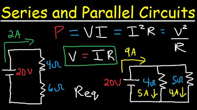
- 🌡️ Power consumption in a circuit can be calculated using the formulas: P = V^2/R or P = VI.
- 🔧 In a parallel circuit, if one component fails, the others continue to operate, as there are multiple paths for current flow.
- 📈 The current through each resistor in a parallel circuit can be calculated by dividing the voltage across it by its resistance.
- 🔄 The total power consumed by a parallel circuit is the sum of the power consumed by each individual component.
- 📊 To find the current in an unknown branch of a parallel circuit, subtract the known branch currents from the total current and apply Ohm's law.
Q & A
What is the primary difference between series and parallel circuits?
-In a series circuit, there is only one path for the electrons to flow along, whereas in a parallel circuit, there are multiple paths for electron flow. If a component fails in a series circuit, the entire circuit stops working, but in a parallel circuit, the other paths continue to function.
How does electron flow differ between conventional flow and electron flow?
-Conventional flow is from positive to negative, which is an older theory and still taught because it is easier to understand. However, electron flow, which is the actual occurrence, is from negative to positive.
What is the voltage across the ends of a parallel circuit connected to a 1.5-volt battery?
-The voltage across the ends of a parallel circuit connected to a 1.5-volt battery is 1.5 volts. Each component or path in a parallel circuit experiences the full voltage of the battery since they are connected directly to both the positive and negative terminals.
How does the total current in a parallel circuit relate to the currents in each branch?
-The total current in a parallel circuit is the sum of the currents in each branch. If multiple resistors are connected in parallel, the total current is the cumulative flow of electrons through all the different routes available.
What happens to the current when a second resistor is added in parallel to a circuit?
-When a second resistor is added in parallel, the total current in the circuit increases. The current divides among the available paths, and each path's current depends on its resistance. The total current is the sum of the currents through each resistor.
How does the voltage affect the current in a circuit?
-As the voltage applied to a circuit increases, the current also increases. This is because a higher voltage difference across a component forces more electrons to flow through it, resulting in a higher current.
What is the formula to calculate the total resistance in a parallel circuit?
-The formula to calculate the total resistance (RT) in a parallel circuit is RT = 1 / (1/R1 + 1/R2 + ... + 1/Rn), where R1, R2, ..., Rn are the resistances of the individual resistors in the circuit.
How can you find the current flowing in a branch if you know the total current and the current in another branch?
-To find the current flowing in a branch, you subtract the known branch current from the total current. For example, if the total current is 3 amps and one branch has a current of 1.8 amps, the current in the other branch is 3 - 1.8 = 1.2 amps.
What are the two formulas to calculate power consumption in a circuit?
-The two formulas to calculate power consumption in a circuit are P = V^2 / R (where P is power in watts, V is voltage in volts, and R is resistance in ohms) and P = V * I (where I is current in amperes).
How does power consumption differ between individual components and the total circuit in a parallel circuit?
-Individual components consume power based on their resistance and the current flowing through them. The total power consumption of the circuit is the sum of the power consumed by each component. It can also be calculated by multiplying the total voltage by the total current in the circuit.
What is the total resistance of a parallel circuit with two 10-ohm resistors?
-The total resistance of a parallel circuit with two 10-ohm resistors is 5 ohms. This is calculated using the formula for total resistance in parallel circuits: RT = 1 / (1/R1 + 1/R2), which in this case is 1 / (1/10 + 1/10) = 1 / (2/10) = 5 ohms.
Outlines
🔌 Introduction to Parallel Circuits and Voltage
This paragraph introduces the concept of parallel circuits, emphasizing their function and calculation methods. It explains the difference between series and parallel connections, and the use of electron flow animation from negative to positive, contrasting with conventional flow. The importance of understanding these concepts is highlighted, as they form the basis for comprehending how circuits work. The paragraph also delves into the behavior of voltage in parallel circuits, using analogies like water pressure to explain the concept of voltage difference and how it can be measured. It clarifies that in parallel circuits, the voltage remains constant across all components because each is directly connected to the battery terminals.
💡 Current Flow and Resistance in Parallel Circuits
This section discusses the behavior of current in parallel circuits, using examples to illustrate how current divides among different paths and how this division is influenced by the resistance of each path. It explains the relationship between voltage, current, and resistance through Ohm's law and provides examples to demonstrate how changes in voltage or resistance affect the total current. The paragraph also addresses how to calculate the current in individual branches and the total current in the circuit, offering practical formulas and methods for these calculations. Additionally, it introduces the concept of total resistance in a parallel circuit and hints at a more detailed explanation to follow, promising to make the typically challenging concept easier to understand with the help of an online calculator.
🔧 Calculating Total Resistance in Parallel Circuits
This paragraph provides a detailed explanation of how to calculate the total resistance in a parallel circuit, which is a concept that often confuses people. It contrasts the straightforward addition of resistances in series circuits with the more complex calculation required for parallel circuits. The explanation includes a step-by-step breakdown of the formula for total resistance in a parallel circuit, using an example with two 10-ohm resistors to demonstrate the process. The paragraph also explains the rationale behind using 'one divided by resistor' fractions in the formula, relating it to the concept of conductance, which is the reciprocal of resistance. It reassures that while the explanation may not be essential for practical calculations, understanding the formula is key. The section concludes with a discussion on power consumption in parallel circuits, explaining how to calculate the power consumed by individual components and the total power consumption using different formulas.
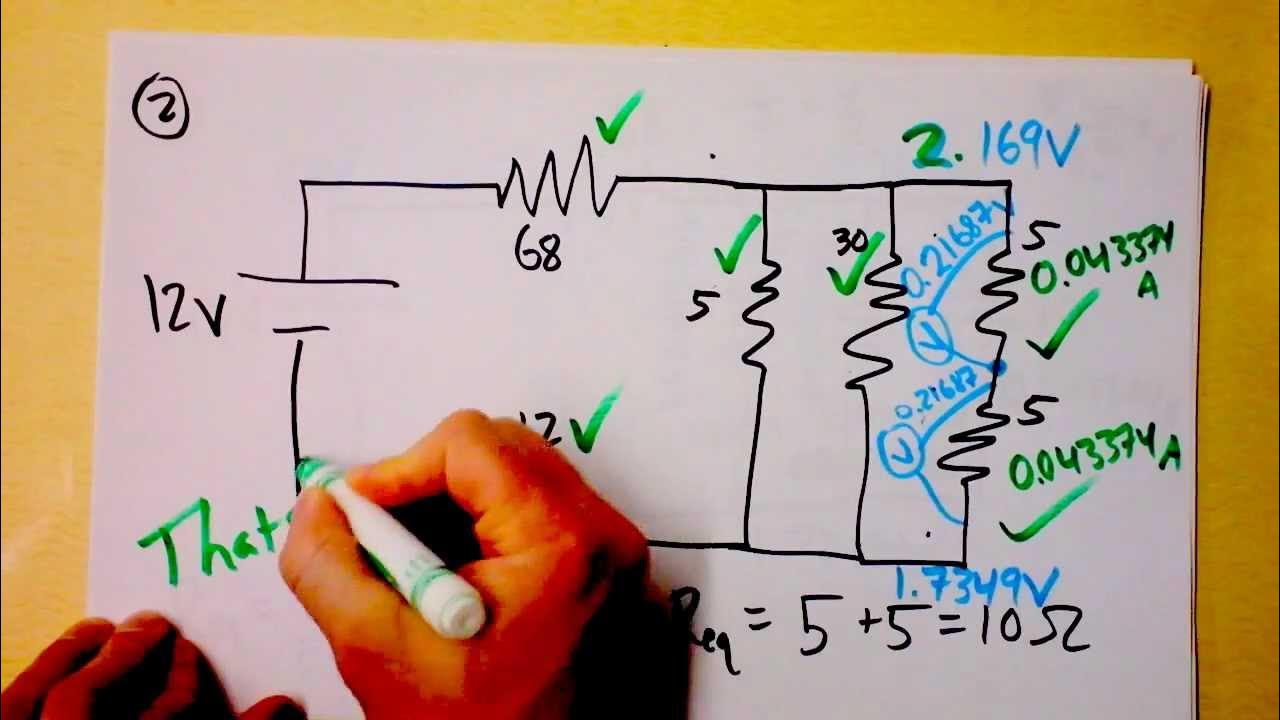
📝 Problem Solving in Parallel Circuits
The final paragraph shifts focus to problem-solving in the context of parallel circuits. It poses two practical problems involving the calculation of total resistance and current flow in circuits with multiple resistors. The first problem involves calculating the total resistance of a circuit with four resistors of varying ohms connected in parallel. The second problem is more complex, requiring the calculation of unknown currents and resistances in a three-resistor parallel circuit, given the total current and the current through one of the resistors. These problems are designed to test the viewer's understanding of the concepts discussed in the video and to apply the formulas and methods introduced earlier. The paragraph concludes with an invitation to continue learning through further videos and encourages viewers to follow the channel on various social media platforms.
Mindmap
Keywords
💡Parallel Circuits
💡Electron Flow
💡Voltage
💡Current
💡Resistance
💡Ohm's Law
💡Total Resistance in Parallel
💡Power Consumption
💡Conductance
💡Circuit Components
💡Electrical Energy Conversion
Highlights
Introduction to parallel circuits and their function
Comparison between electron flow and conventional flow
Explanation of series and parallel configurations
The effect of a broken bulb in a series circuit, like fairy lights
Advantages of wiring lamps in parallel for fault tolerance
Understanding voltage in parallel circuits and its consistency
Comparison of voltage measurement in series and parallel circuits
Explanation of current flow in parallel circuits and its division
Calculation of total current in a parallel circuit with examples
Explanation of Ohm's law and its application in calculating current
Demonstration of how voltage affects current in a circuit
Detailed calculation of current through individual resistors in parallel
Introduction to calculating total resistance in a parallel circuit
Explanation of the formula for total resistance in parallel circuits
Use of a free online calculator for finding total resistance in parallel circuits
Explanation of power consumption in parallel circuits and its calculation
Practical examples of power consumption calculation for individual components
Problem-solving section for viewers to apply their understanding of parallel circuits
Transcripts
Browse More Related Video
Series and Parallel Circuits

Electricity - Basic Introduction

DC Resistors & Batteries: Crash Course Physics #29

Essential & Practical Circuit Analysis: Part 1- DC Circuits
Parallel and Series Resistor Circuit Analysis Worked Example using Ohm's Law Reduction | Doc Physics

High School Physics - Parallel Circuits
5.0 / 5 (0 votes)
Thanks for rating: