Basic Electronic Components With Symbols And Functionality.
TLDRThis video script offers an insightful overview of electronic component symbols used in circuit diagrams, emphasizing their standardized nature despite variations by country. It covers a wide array of components, including antennas, capacitors, power supplies, diodes, transistors, and switches, explaining their functions and symbols. The script also touches on measurement instruments like ammeters and voltmeters, highlighting the importance of these symbols in electronic design and safety.
Takeaways
- 📡 The antenna is a key component for sending and receiving radio signals in all radio equipment.
- 🔌 The capacitor, also known as a condenser, stores electrical energy in an electric field and is measured in farads, with types including polarized and non-polarized.
- 🔋 A power supply symbol in a circuit represents the conversion of chemical energy into electrical potential energy, with terminals marked by parallel lines.
- 🔌 AC and DC circuits differ in the direction of electrical charge flow, with AC having a wavy line and DC a straight line inside a circle.
- 💡 Fuses are safety devices made of thin metallic wire that melt if the current exceeds a specified value, symbolized by a specific form in circuit diagrams.
- 🔄 Transformers transfer electric energy between circuits, stepping up or down voltage, represented by two coils separated by parallel lines.
- ⚡ Diodes allow current to flow in one direction only, symbolized by a triangle pressed against a line in circuit diagrams.
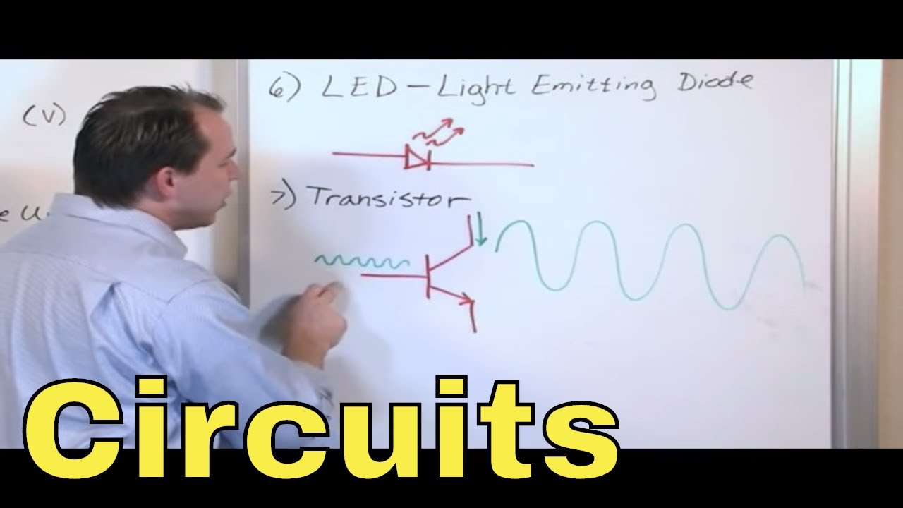
- 💡 LEDs emit light when current flows through them, with the color depending on the semiconductor material, symbolized with arrows denoting light emission.
- 🔬 Photodiodes convert light into electric current when photons are absorbed, symbolized similarly to pn junction diodes with arrows representing light.
- 🔌 Resistors impede the flow of electricity, with two main circuit symbols, one jagged line in North America and a small rectangle in Europe and Asia.
- 🔄 Variable resistors, including rheostats and potentiometers, allow for the adjustment of resistance to control voltage or current in a circuit.
Q & A
What is an electronic component symbol used for in a circuit diagram?
-An electronic component symbol is used to denote various electrical and electronic devices or functions in a circuit diagram, which is essential for designing circuits for projects.
What is the primary function of an antenna in electronic circuits?
-An antenna is used for sending and receiving radio signals and is an essential component of all radio equipment.
What is a capacitor and how is it represented in a circuit diagram?
-A capacitor, also known as a condenser, is a device that stores electrical energy in the form of an electric charge in an electrical field. It is represented by two parallel plates placed between two terminals.
How are capacitors classified according to polarization?
-Capacitors are classified into polarized and non-polarized types. Polarized capacitors can only be used in one polarity due to their construction, while non-polarized capacitors can be used in any direction because they have no implicit polarity.
What is the difference between a variable capacitor and a fixed capacitor?
-A variable capacitor is defined as one whose capacitance can be varied based on the requirement within a certain range of values, indicated by an arrow on its symbol. A fixed capacitor stores a fixed amount of electric charge and is not adjustable.
What does a power supply symbol represent and how is it depicted in a circuit diagram?
-A power supply symbol represents an electrical power source that converts stored chemical energy into electrical potential energy. It is depicted with two parallel lines at right angles to the connecting wires, with the thinner line marking the positive terminal and the thicker, shorter line marking the negative terminal.
What is the role of a fuse in an electrical circuit?
-A fuse is a safety device made of a thin strip or strand of metallic wire that melts if the current flowing through it exceeds a specified value, thereby protecting the circuit from damage.
How does a transformer function and what is its symbol in a circuit diagram?
-A transformer transfers electric energy from one alternating current circuit to one or more circuits, stepping up or stepping down the voltage. Its symbol is denoted by two coils placed side by side and separated by parallel lines.
What is a diode and how is it represented in a circuit diagram?
-A diode is a device that allows current to flow through it in one direction only. It is represented by a horizontal isosceles triangle pressed up against a line between two terminals.
What is the purpose of a resistor and how is it symbolized in a circuit diagram?
-A resistor impedes the flow of electricity through a circuit and is used in virtually all electronic circuits. It is symbolized by a jagged or wavy line in North America, or a small rectangle in Europe and Asia.
What is the function of a transistor and how does an NPN transistor differ from a PNP transistor?
-A transistor is a semiconductor device for amplifying, controlling, and generating electrical signals. An NPN transistor allows current flow when there is a high potential at the base, with the arrow in its symbol pointing from the base to the emitter. A PNP transistor, on the other hand, has the current flow from the emitter to the collector, with the arrow pointing from the emitter to the base.
Outlines
🔌 Basic Electronic Components and Their Symbols
This paragraph introduces the fundamental electronic components and their standardized symbols used in circuit diagrams. It covers the antenna for radio signal transmission, capacitors which store electrical energy, and their types, including polarized and non-polarized. The paragraph also explains power supplies, such as cells and batteries, AC and DC circuits, fuses for safety, and transformers for voltage transfer. Additionally, it touches on diodes, including standard, LED, zener, photodiode, tunnel, and Schottky diodes, each with its unique function and symbol in electronic circuits.
📏 Measuring Instruments and Resistors in Electronics
The second paragraph delves into the various instruments used for measuring electrical properties, such as ammeters, galvanometers, ohmmeters, oscilloscopes, voltmeters, and the significance of resistors in controlling electrical flow. It highlights different types of resistors, including fixed and variable resistors, rheostats, potentiometers, and their symbols. The paragraph emphasizes the importance of these components in electronic circuits for adjusting voltage, current, and resistance.
🔬 Semiconductor Devices: Transistors and Their Applications
This section focuses on semiconductor devices, particularly transistors, which are crucial for amplifying and controlling electrical signals. It differentiates between NPN and PNP transistors, explains their symbols, and discusses phototransistors and field-effect transistors, including JFETs and MOSFETs. The paragraph also covers the operation of depletion and enhancement mode transistors, highlighting their roles in modern integrated circuits and electronic devices.
🔄 Switches, Relays, and Inductors in Circuit Control
The final paragraph discusses switches used to make or break circuits, including push switches and single pole single throw switches. It explains double pole single throw and double pole double throw switches, which control multiple circuit poles and outputs. The paragraph also introduces relays as electromagnetic switches and inductors that store energy in a magnetic field, detailing their symbols and functions within electrical circuits.
Mindmap
Keywords
💡Electronic Component Symbol
💡Capacitor
💡Power Supply
💡AC and DC Circuits
💡Fuse
💡Transformer
💡Diode
💡Ammeters and Galvanometers
💡Ohmmeter
💡Oscilloscope
💡Resistor
💡Variable Resistor and Potentiometer
💡Transistor
💡Switch
💡Inductor
💡Relay
Highlights
Electronic component symbols are essential for circuit design and are largely standardized internationally.
Component symbols may vary by country but adhere to ANSI and IEC standards.
The antenna is vital for sending and receiving radio signals in all radio equipment.
Capacitors store electrical energy and are classified as polarized or non-polarized based on their construction.
Variable capacitors can have their capacitance adjusted within a certain range, indicated by an arrow on their symbol.
Power supply symbols represent the conversion of chemical energy into electrical potential energy.
AC and DC circuit symbols distinguish between alternating and direct current flow.
Fuses are safety devices that melt when the current exceeds a specified value, represented by a specific symbol.
Transformers transfer electric energy between circuits, stepping up or down voltage, symbolized by two coils.
Diodes allow current flow in one direction only, symbolized by a triangle pressed against a line.
LEDs emit light based on the semiconductor material used, with a symbol that includes arrows for light emission.
Zener diodes allow current to flow backward at a certain reverse voltage, distinguished by a bent line in their symbol.
Photodiodes convert light into electric current, symbolized with arrows representing photons striking the diode.
Tunnel diodes show negative resistance and work based on the tunnel effect, symbolized by a unique diode symbol.
Schottky diodes have less forward voltage drop than PN junction diodes and are used in high-speed switching.
Meters such as ammeters, galvanometers, and ohmmeters are used to measure various electrical effects.
Oscilloscopes display and analyze electronic signal waveforms, symbolized by a wavy line in a circle.
Voltmeters measure electrical potential difference and are represented by the letter 'V' in a circle.
Resistors impede electricity flow and have two main circuit symbols, one jagged and one rectangular.
Variable resistors, or rheostats, can adjust resistance and are symbolized by a rectangle with an arrow.
Potentiometers are three-terminal resistors used as variable voltage dividers, symbolized with an arrow mark.
Transistors are semiconductor devices for signal amplification and control, with various types including NPN and PNP.
Phototransistors sense light levels and alter current flow, symbolized with arrows pointing towards the junction.
Field effect transistors, including JFETs and MOSFETs, are used for weak signal amplification and switching.
Switches interrupt current flow in a circuit and have various configurations like SPST, SPDT, DPST, and DPDT.
Inductors store energy in a magnetic field and are symbolized by a coil or spiral in a circuit.
Relays are electromagnetic switches controlled by a small current to operate a larger current, symbolized by a box and contacts.
Transcripts
Browse More Related Video

Circuit symbols (SP10a)
02 - Overview of Circuit Components - Resistor, Capacitor, Inductor, Transistor, Diode, Transformer

Circuit symbols

How to read schematic diagrams for electronics part 1 tutorial: The basics

A simple guide to electronic components.
How to use a multimeter like a pro! The Ultimate guide
5.0 / 5 (0 votes)
Thanks for rating: