How to use a multimeter like a pro! The Ultimate guide
TLDRThis informative video script offers a comprehensive guide on using multimeters, emphasizing their ease of use and diverse functionalities. It covers both analog and digital multimeters, but focuses on the latter, highlighting the benefits of auto and manual range versions. The script delves into measuring various electrical properties like voltage, current, resistance, frequency, and temperature, and provides safety tips for accurate and risk-free usage. It also touches on testing components like diodes, LEDs, capacitors, and transistors, and suggests resources for further learning.
Takeaways
- 🔍 Multimeters, despite their complexity, are quite easy to use once you understand their basic functions and features.
- 📚 There are two main types of multimeters: analog and digital. Digital multimeters are more user-friendly and offer more functions than analog ones.
- 🎯 Auto Range multimeters automatically determine the correct range for the measurement, making them faster and easier to use, but they are typically more expensive.
- 🔧 Digital multimeters measure basic functions like voltage, current, and resistance, and some advanced models can measure capacitors, transistors, diodes, temperature, and more.
- 🔌 When measuring DC voltage, connect the red lead to the V terminal and the black lead to the COM terminal, and ensure the multimeter is set to the correct DC voltage setting.
- ⚡ For AC voltage measurements, follow safety precautions and ensure the multimeter is set to the AC voltage setting. Use socket testers for household circuits for added safety.
- 🌡️ To measure resistance, use the resistance setting on the multimeter and connect the leads across the component. Auto Range multimeters will display the result, while manual range versions require selecting the correct scale.
- 🔍 Continuity tests can be performed to check if two points in a circuit are connected, using the continuity function or by testing the resistance between the points.
- 📊 Frequency can be measured by inserting the leads into the appropriate terminals and selecting the frequency function on the multimeter.
- 🔋 Capacitors can be tested for stored voltage by using the DC voltage setting, and their capacitance can be measured using the capacitor setting on the multimeter.
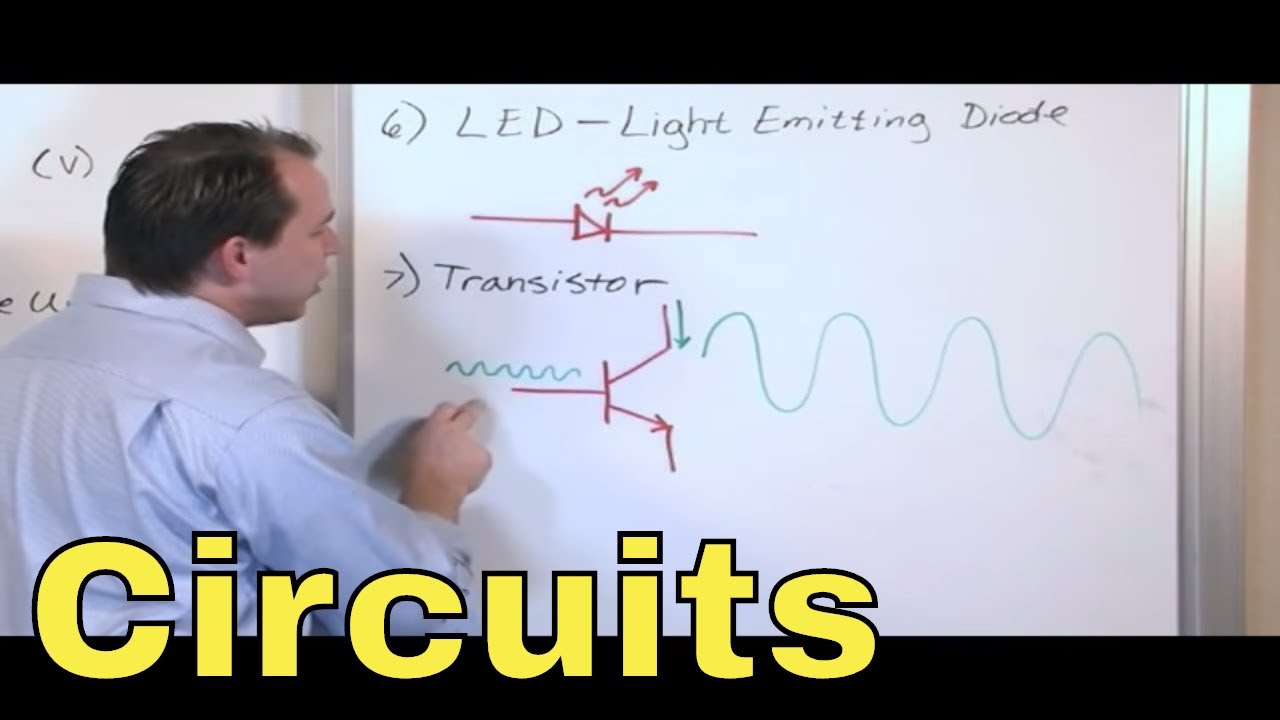
- 🔌 Transistors can be tested using the hFE setting on a multimeter, and diodes can be checked for functionality by measuring their resistance in both directions.
Q & A
What are the two main types of multimeters mentioned in the script?
-The two main types of multimeters mentioned are analog and digital multimeters.
Why are analog multimeters considered less favorable compared to digital multimeters?
-Analog multimeters are considered less favorable because they use a dial that is difficult to use and read, and they usually only have a few basic functions.
What are the primary functions that all multimeters are designed to measure?
-All multimeters are designed to measure voltage, current, and resistance.
What is the difference between manual range and auto range digital multimeters?
-With manual range multimeters, the user has to select the correct range to get the correct answer, while auto range multimeters automatically determine the appropriate range and provide the answer, making them easier and faster to use.
What is the symbol used to represent DC voltage and why is it used?
-The symbol used to represent DC voltage is not explicitly mentioned in the script, but it is typically a straight line with an arrow. It is used because DC (direct current) electrons flow in one direction, similar to the flow of water in a river.
How do you measure the voltage of a circuit component?
-To measure the voltage of a circuit component, connect the multimeter's red lead to the positive terminal and the black lead to the negative terminal of the component. Then, select the appropriate voltage setting on the multimeter.
What safety precautions should be taken when measuring AC voltage?
-When measuring AC voltage, ensure the red lead is in the V terminal and the black lead is in the COM terminal. Keep fingers away from the probe tips, use well-insulated cables, and never use or repair a damaged cable. Always connect the black wire to the neutral first and avoid using the multimeter in wet conditions.
How can you measure the resistance of a component using a multimeter?
-To measure resistance, place the black lead into the COM terminal and the red lead into the terminal with the ohm symbol. For auto range devices, select the resistance setting and connect the leads across the component. For manual range devices, select the next higher value setting.
What does the symbol for frequency measurement represent and how is it related to AC electricity?
-The symbol for frequency measurement represents the number of times the pattern of an electrical signal repeats per second. It is related to AC electricity because AC current alternates direction, and the frequency indicates how often this change occurs, such as 60 hertz in North America or 50 hertz in Europe.
How can you test a diode with a multimeter?
-To test a diode with a multimeter, set the dial to the diode setting, connect the red lead to the diode terminal and the black lead to the COM terminal. If the diode is functioning correctly, you should read 'OL' when connected in the forward direction and a value between 0.5 and 0.8 when the leads are reversed.
What is the process for testing a capacitor's stored voltage?
-To test a capacitor's stored voltage, select the DC voltage setting on the multimeter. Place the black lead into the COM terminal and the red lead into the V terminal, then connect the probes to the capacitor terminals. If the capacitor is polarized, ensure the black probe touches the negative terminal. The multimeter will display the stored voltage.
How can you use a multimeter to check the functionality of a transistor?
-To check a transistor's functionality, use the hFE setting on the multimeter. Locate the transistor's identification number, find the corresponding data sheet, and determine the transistor type (NPN or PNP). Insert the transistor legs into the correct terminals on the multimeter and it will display the hFE value. If the value is within the specified range, the transistor is good to use.
Outlines
🔧 Introduction to Multimeters and Basic Functions
This paragraph introduces the viewer to multimeters, addressing common concerns about their complexity and variety. It explains that while there are many types of multimeters, the focus of the video will be on digital multimeters, which are user-friendly and feature-rich. The video also mentions the availability of a multimeter PDF book and sponsorship by PCB way, a company offering various electronic fabrication services. The basic functions of multimeters, such as measuring voltage, current, and resistance, are briefly touched upon, setting the stage for more in-depth explanations in the subsequent paragraphs.
⚡ Measuring DC Voltage and Safety Precautions
The second paragraph delves into the specifics of measuring DC voltage, which is found in sources like batteries and electronic devices. It explains the symbol for DC voltage and the procedure for measuring it using a multimeter, including the correct placement of leads and interpreting readings. The paragraph emphasizes safety when dealing with electrical sockets and recommends using socket testers for AC voltage measurements. It provides detailed instructions on how to measure AC voltage for different types of electrical systems, such as North American, British, Australian, and European circuits, and highlights the importance of following safety guidelines to prevent electric shock.
🔍 Understanding Resistance and Current Measurement
This paragraph focuses on measuring resistance and current using a multimeter. It defines resistance and explains how it can be measured using the ohm setting on the multimeter. The paragraph also discusses the importance of isolating components before testing and the impact of temperature on resistance readings. For current measurement, it describes the process of placing the multimeter in series with the circuit and the necessary precautions to avoid damaging the multimeter. The paragraph further explains how to measure both DC and AC current, offering practical advice on using clamp meters for AC current and energy monitors for device current measurement.
🔌 Testing Components like Diodes, LEDs, Capacitors, and Transistors
The fourth paragraph provides an in-depth look at using a multimeter to test various electronic components such as diodes, LEDs, capacitors, and transistors. It explains the forward and reverse bias testing for diodes, the resistance range for LEDs, and the safe discharge of capacitors. The paragraph also covers how to test the capacitance of capacitors and the process of checking transistors using the hFE setting or the diode setting as an alternative method. The information is practical and aimed at helping viewers understand the functionality and testing of these components through hands-on demonstrations.
🌡️ Measuring Temperature and Battery Testing
The final paragraph discusses the use of a multimeter for temperature measurement and battery testing. It explains how to use a temperature probe and the importance of correct polarity when connecting it to the multimeter. The paragraph then moves on to describe how to test batteries by measuring their voltage under no load and under load conditions, providing insights into determining the health of a battery. The video concludes with an encouragement for viewers to continue learning about electronics engineering and a reminder to follow the channel on various social media platforms.
Mindmap
Keywords
💡multimeter
💡analog vs digital multimeters
💡Auto Range vs manual range
💡DC voltage
💡AC voltage
💡resistance
💡continuity
💡diodes
💡capacitors
💡transistors
💡temperature measurement
Highlights
Multimeters are easier to use than they appear, with various designs and functions.
Analog multimeters are less commonly used today due to their difficulty in reading and limited functions.
Digital multimeters offer precision, ease of use, and a wider range of functions compared to analog versions.
Auto Range digital multimeters provide the simplest and fastest measurements but are typically more expensive.
Multimeters measure basic functions like voltage, current, and resistance, with advanced models measuring additional parameters like temperature and capacitance.
Measuring DC voltage involves connecting the multimeter probes to the positive and negative terminals of a power source.
AC voltage measurements require safety precautions and correct probe placement to avoid electrical hazards.
Socket testers are recommended for safer AC voltage measurements in home electrical outlets.
Measuring resistance involves understanding the ohm symbol and the correct terminal placement for the multimeter leads.
Current measurement requires the multimeter to be in series with the circuit, with specific attention to the correct terminals and safety.
True RMS multimeters are recommended for more accurate electrical waveform measurements.
Continuity tests can be performed using the multimeter to check for electrical connections in a circuit.
Frequency measurements are related to the speed of the electrical generator and can be read using a multimeter.
Diode testing involves checking their ability to allow current flow in one direction and can be done using the diode setting on a multimeter.
LEDs and capacitors can also be tested using multimeters, with specific procedures for each component.
Transistors are electronic switches that can be tested using the hFE setting on a multimeter, requiring knowledge of their type and correct terminal alignment.
Temperature readings can be taken using a multimeter with a temperature probe, typically for air or surface temperatures.
Battery testing involves measuring both the voltage under no load and the voltage under a small load to determine the battery's health.
Transcripts
Browse More Related Video

How to use a multimeter like a pro, the ultimate guide

Why The Clamp Meter Is The Only Tester You Need | Pros and DIYers
02 - Overview of Circuit Components - Resistor, Capacitor, Inductor, Transistor, Diode, Transformer

How to read schematic diagrams for electronics part 1 tutorial: The basics

The Best Multimeter Tutorial in The World (How to use & Experiments)

Basic Electronic Components With Symbols And Functionality.
5.0 / 5 (0 votes)
Thanks for rating: