The Maths Prof: Calculate Bearings
TLDRIn this educational video, the host explains the concept of bearings, which are specific angles measured from the north arrow and in a clockwise direction. The video demonstrates how to calculate bearings with three examples. First, it shows that the bearing of B from A is 80° and then calculates the reverse bearing as 260°. The second example involves bearings from points C to D and D to C, using angles on parallel lines to find bearings of 110° and 290°, respectively. The third example covers bearings from A to B, B to A, and B to C, with bearings calculated as 60°, 240°, and 350°. The host emphasizes that diagrams in such problems are not to scale and that bearings are always three-figure numbers, highlighting the importance of understanding parallel lines and corresponding angles for solving these types of questions.
Takeaways
- 🧭 Bearings are special angles measured from the north arrow in a clockwise direction.
- 🔢 Bearings are always expressed as three-figure numbers, even if leading zeros are required.
- 📐 To find the bearing from point A to B, start at the north arrow of A and draw an arrow clockwise until it hits the line to B.
- 🔄 The concept of clockwise measurement is crucial, as bearings are always measured in this direction.
- ↔️ Bearings can be calculated using the properties of parallel lines and corresponding angles.
- 📏 Angles on a straight line sum up to 180°, which is useful for calculating bearings.
- 🔵 Diagrams used in bearing problems are often not to scale and may not reflect actual measurements.
- 🔴 The first step in solving a bearing problem is to identify the starting point (the north arrow of the reference point).
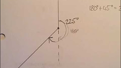
- 🟢 When calculating the bearing of a point from another, consider the full 360° of a circle where necessary.
- 📐 Use a protractor for measuring angles only when diagrams are explicitly stated to be to scale.
- ⏹️ The video script emphasizes that diagrams are for illustrative purposes and may not represent actual distances or angles.
Q & A
What are bearings and how are they different from regular angles?
-Bearings are special angles that are always measured from the north arrow and in a clockwise direction, similar to how a clock moves. They are different from regular angles because they must always be three figures long, even if that means adding a zero to the beginning.
Why is it necessary to measure bearings in a clockwise direction?
-Bearings are measured in a clockwise direction to maintain consistency and standardization in how these angles are taken. This method ensures that bearings are interpreted and understood in the same way by everyone.
How do you determine the bearing of point B from point A on a diagram?
-To determine the bearing of B from A, you start at the north arrow of point A, draw an arrow clockwise until it hits the line that travels to point B, and then measure the angle. The angle is then labeled with three figures, adding a zero if necessary.
What is the bearing of point A from point B in the first example of the script?
-In the first example, the bearing of A from B is calculated by adding the angle of 80° to the 180° of the straight line, resulting in a bearing of 260°.
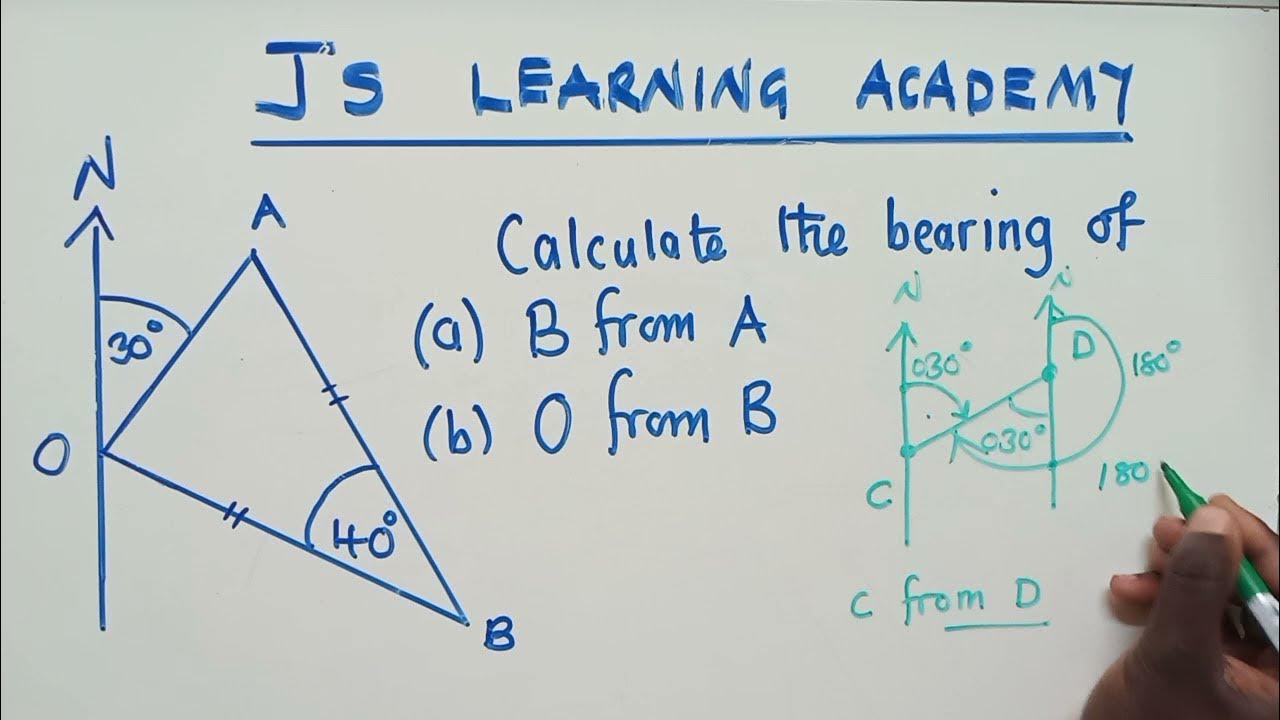
How do you find the bearing of point D from point C given the angle of 70° in the second example?
-Since the angle is 70° and angles on a straight line add up to 180°, the bearing of D from C is found by subtracting 70° from 180°, which gives a bearing of 110°.
What is the bearing of point C from point D in the second example?
-The bearing of C from D is found by recognizing that angles in a circle add up to 360°. If one angle is 70°, the remaining angle must be 360° - 70°, which is 290°.
In the third example, what is the bearing of point B from point A?
-The bearing of B from A in the third example is already given as 60°, which is a three-figure bearing as per the standard for bearings.
How do you calculate the bearing of point A from point B in the third example?
-The bearing of A from B is calculated by adding the angle of 60° to the 180° of the straight line, resulting in a bearing of 240°.
What is the bearing of point B from point C in the third example?
-The bearing of B from C is found by adding the angle of 170° to the 180° of the straight line, but since the angle is already part of the 180°, the bearing is actually 350°.
Why are the diagrams used in the examples not to scale?
-The diagrams are not to scale to illustrate the concept of bearings without the need for precise measurements. In practical applications, a protractor would be used for accurate measurements, and the diagrams would be to scale.
When would you use a protractor to measure angles on a diagram?
-A protractor would be used when the diagram is to scale, and precise measurements are necessary, such as in real-world navigation or architectural planning.
What is the significance of the zero in the three-figure bearing notation?
-The zero in the three-figure bearing notation is used to ensure that all bearings are represented with three digits, making them easier to read and compare, especially when dealing with bearings close to multiples of 10°.
Outlines
🧭 Understanding Bearings and Their Calculation
This paragraph introduces the concept of bearings, which are special angles measured from the north arrow and in a clockwise direction. It emphasizes the need for bearings to be three-figure numbers and explains how to plot them on a diagram. The video demonstrates how to find the bearing of point B from point A, which is given as 80°, by drawing an arrow from the north arrow of A to point B. It also covers how to find the reciprocal bearing of A from B, using the properties of parallel lines and corresponding angles. The process involves extending lines to identify corresponding angles and using the fact that angles on a straight line sum up to 180° to calculate the bearing. The example concludes with the bearing of A from B being 260°.
📐 Applying Angle Rules to Find Bearings
The second paragraph continues the discussion on bearings with an example involving points C and D. It explains how to find the bearing of D from C, given an angle of 70°, by using the north arrow of C and drawing a clockwise arrow to point D. Utilizing the rules of angles on parallel lines, the presenter shows that the bearing of D from C is 110°. For the bearing of C from D, the process is reversed, starting at the north arrow of D. The video demonstrates that angles in a circle add up to 360°, and by subtracting the given angle of 70°, the bearing of C from D is found to be 290°. The example concludes with a reminder that the diagrams used are not to scale and that actual measurements would be unlikely to match the provided angles.
Mindmap
Keywords
💡Bearings
💡North Arrow
💡Clockwise
💡Three-Figure Bearing
💡Parallel Lines
💡Corresponding Angles
💡Straight Line
💡Protractor
💡Not to Scale
💡Diagram
💡Angles on a Straight Line
Highlights
Bearings are special angles measured from the north arrow.
Bearings are always measured in a clockwise direction.
Three-figure bearings are used to maintain consistency in notation.
The bearing of B from A is given as an example with a value of 80°.
North arrows are added to diagrams when not already present.
The process of finding the bearing of A from B is demonstrated.
Parallel lines and corresponding angles are key to solving bearing problems.
Angles on a straight line sum up to 180°, used to calculate bearings.
The bearing of A from B is calculated to be 260°.
The bearing of D from C is found using the rule of 180° minus the given angle.
The bearing of C from D is calculated by subtracting the known angle from 360°.
Angles in a circle always add up to 360°, used to find the bearing of C from D.
The bearing of B from A is given as 60° in the third example.
The bearing of A from B is calculated by adding 60° to 180°, resulting in 240°.
The bearing of B from C is solved by adding two corresponding angles and 180°.
The final bearing calculated in the third example is 350°.
Diagrams used in bearing problems are often not to scale.
Scale and use of a protractor in bearing problems will be covered in a future video.
Transcripts


5.0 / 5 (0 votes)
Thanks for rating: