Lesson 1 - Voltage, Current, Resistance (Engineering Circuit Analysis)
TLDRThis script introduces the fundamentals of electrical engineering and circuit analysis. It emphasizes the importance of understanding the basic concepts of voltage, current, and resistance, which form the backbone of any electrical circuit. The video explains that voltage is the driving force, current represents the flow of electrons, and resistance opposes this flow. It also distinguishes between direct current (DC) and alternating current (AC), highlighting their applications and differences. The script further clarifies the meaning of open and short circuits, and their implications in real-world scenarios. The goal is to make the subject accessible, with a focus on practice and the application of basic algebra for analysis, making it relevant to both beginners and engineering students.
Takeaways
- 🎓 The course focuses on engineering circuit analysis, aiming to make complex electrical engineering concepts accessible to everyone.
- 🔋 A circuit is fundamentally a closed loop that carries electricity, and it can be as simple as a wire connected to a battery.
- 🔌 Electric current (I) is the flow of electrons in a circuit. In engineering, we often represent this flow as 'hole current' for mathematical convenience.
- ⚡ Voltage (V) is the push that causes current to flow. It is the potential difference offered by a power source like a battery or a wall socket.
- 🛡️ Resistance (R) opposes the flow of current in a circuit and is related to the size and material of the conducting path; larger cross-sections offer lower resistance.
- ⚙️ The units for current, voltage, and resistance are amperes (A), volts (V), and ohms (Ω), respectively, with metric prefixes used for different magnitudes.
- 🔄 The concepts of voltage, current, and resistance are interrelated and form the basis for understanding and analyzing circuits.
- 🔄 DC (Direct Current) comes from batteries and provides a constant voltage and current flow, whereas AC (Alternating Current) is the type of electricity supplied by wall sockets and changes direction periodically.
- 🚫 An open circuit is a broken path in the circuit that prevents current flow, while a short circuit is an unintended low-resistance path that can cause excessive current and potential damage.
- 💡 The knowledge gained from learning about circuits can be practically applied to build various electronic devices, making it a valuable skill with real-world applications.
Q & A
What is the main focus of the engineering circuit analysis course mentioned in the transcript?
-The main focus of the engineering circuit analysis course is to teach the fundamentals of circuits, how to analyze them, understand the components that go into circuits, and the principles behind their operation. The course aims to make the subject accessible to everyone, regardless of their background in engineering.
What is the definition of an electric circuit?
-An electric circuit is a closed loop that carries electricity. For a circuit to function, it must be complete, allowing electricity to flow from the source, through the circuit elements, and back to the starting point.
What is the difference between voltage and current in electrical circuits?
-Voltage is the push or electrical pressure that causes current to flow in a circuit. It is measured in volts (V). Current, on the other hand, is the flow of electrons in a circuit, which is measured in amperes (A). Voltage can be thought of as the cause of current flow, while current is the result or effect.
Why is it important to understand the concepts of voltage, current, and resistance?
-Understanding the concepts of voltage, current, and resistance is crucial because these are the fundamental building blocks of any electrical circuit. They are interconnected and play a significant role in how a circuit operates. Knowing how they work together allows one to analyze and troubleshoot circuits effectively.
What is the role of resistance in an electrical circuit?
-Resistance opposes the flow of current in a circuit. It is a property of the materials and components within the circuit that determines how much they resist the flow of electrons. Resistance can be manipulated to control the amount of current flowing through a circuit, which is essential for the proper functioning of various electrical devices.
What are the units used to measure current, voltage, and resistance?
-The unit used to measure current is the ampere (A), commonly referred to as an amp. Voltage is measured in volts (V), and resistance is measured in ohms (Ω), which is symbolized by the capital Greek letter omega.
What is the difference between DC and AC in electrical circuits?
-DC stands for Direct Current, which refers to a constant and unidirectional flow of electric charge. Batteries are an example of DC sources. AC stands for Alternating Current, which involves a periodic change in the direction of the flow of electric charge. The electricity supplied through wall sockets is an example of AC, which alternates direction many times per second (60 times per second in the United States).
What is an open circuit?
-An open circuit is a condition where the path of the electrical circuit is broken, preventing current from flowing. This can occur when a switch is turned off or when there is a break in the wiring. No electricity can flow in an open circuit by definition.
What is a short circuit and why is it problematic?
-A short circuit occurs when an unintended low-resistance path is created in a circuit, causing a large amount of current to flow through this path. This can be dangerous as it can lead to overheating, damage to circuit components, and even fires. Circuit breakers are used to prevent such occurrences by interrupting the flow of current when a short circuit is detected.
How does the size of a wire affect its resistance?
-The size of a wire, or its cross-sectional area, has an inverse relationship with its resistance. A larger wire will have a lower resistance because more electrons can flow through it simultaneously, reducing the opposition to the flow of current. Conversely, a smaller wire will have a higher resistance because it provides less area for the electrons to flow through, increasing the opposition to the current flow.
What is the significance of Ohm's Law in circuit analysis?
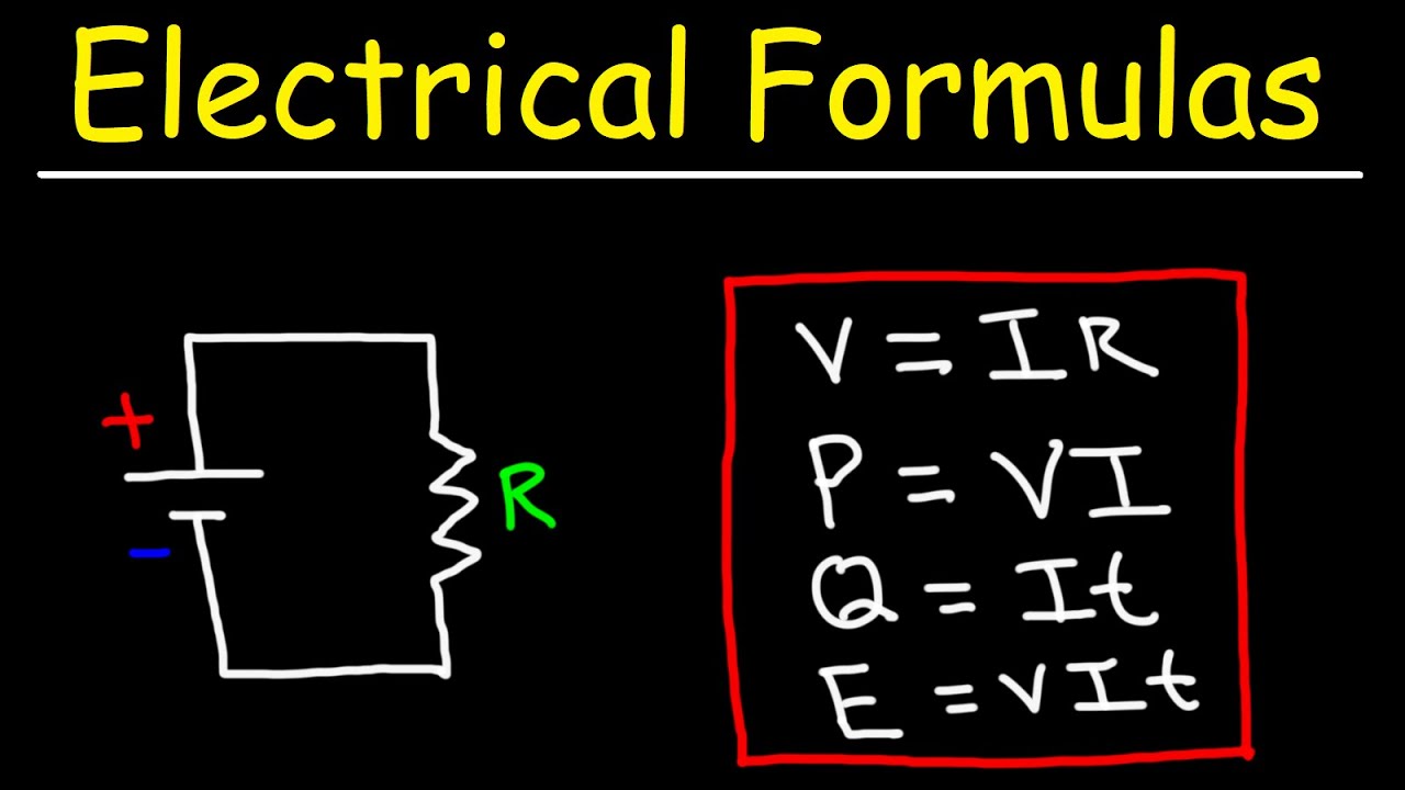
-Ohm's Law is a fundamental principle in circuit analysis that relates voltage (V), current (I), and resistance (R) in a circuit. It states that the voltage across a resistor is directly proportional to the current flowing through it, with the resistance being the constant of proportionality. Ohm's Law is essential for calculating unknown values in a circuit and for understanding how changes in one circuit element can affect the others.
Outlines
🎓 Introduction to Engineering Circuit Analysis
The video begins with an introduction to the course on engineering circuit analysis. The instructor expresses excitement about teaching the course due to their background in electrical engineering. The course aims to provide a comprehensive understanding of circuits, including their components and analysis techniques. The importance of learning the basics is emphasized, as it forms the foundation for understanding complex systems like microchips, amplifiers, and nuclear power plants. The instructor assures that the course will be accessible, focusing on fundamental concepts like voltage, current, and resistance, and requiring only basic algebra for most of the analysis. The goal is to make the subject matter approachable for everyone, while also catering to engineering students.
🔋 Understanding Electric Circuits and Current
This paragraph delves into the definition of an electric circuit, explaining it as a closed loop that carries electricity. It emphasizes the necessity of a complete path for electricity to flow. The concept of electric current is introduced as the flow of electrons in a circuit, likened to the movement of water in a stream. The paragraph describes how electrons in conductive materials like copper can be influenced to move by a power source such as a battery, creating a chain reaction that results in the flow of electric current. The movement of electrons is portrayed as a form of energy that performs useful work within the circuit.
🔄 Electron Flow and the Concept of Hole Current
The explanation continues with a deeper look at electron flow, describing it as a movement from one atom to another within a conductor. However, when analyzing circuits in an engineering context, it's more convenient to consider the flow of positive charges, known as hole current, in the opposite direction to the electron flow. This simplifies the equations used in circuit analysis by eliminating the need to account for negative charges in the equations. The paragraph clarifies that while electrons are the actual charge carriers, in engineering terms, the conventional current is considered to flow from the positive terminal of the power source.
💡 Units of Electric Current and Voltage
This section introduces the units used to measure electric current and voltage. The unit for current is the ampere (amp), which indicates the amount of charge passing through a circuit per second. The paragraph explains that a higher ampere reading indicates a greater flow of current. Voltage is explained as the force or 'push' that causes current to flow, with its unit being the volt (V). The analogy of a straw is used to illustrate how voltage affects the flow of current, with a higher voltage being akin to blowing harder into a straw, leading to more airflow. The paragraph also clarifies that while voltage is often discussed in dangerous contexts, it is the current that actually flows through the body, and voltage indicates the potential for that current to flow.
🛠️ Resistance and Its Impact on Circuits
Resistance is introduced as a property that opposes the flow of current in a circuit. The analogy of air flowing through straws of different sizes is used to explain how resistance is related to the physical size and material of the conductor. The paragraph emphasizes that smaller or thinner conductors have higher resistance and are more effective at opposing the flow of current. The unit for resistance is the ohm (Ω), with larger values indicating greater resistance to current flow. The relationship between current, voltage, and resistance is highlighted, with the understanding that they are all interconnected in circuit analysis.
🔌 Direct Current (DC) vs Alternating Current (AC)
The difference between direct current (DC) and alternating current (AC) is discussed in this paragraph. DC is described as a constant flow of current, typical of batteries and other chemical reactions that provide a steady voltage and current. On the other hand, AC is characterized by its periodic change in direction, which is common in wall sockets and power supplied from the grid. The generation of electricity in power plants involves rotating generators, which naturally produces AC. The paragraph also touches on the reasons why AC is preferred for power transmission and its ease of generation. The importance of understanding both DC and AC is emphasized, as they are both forms of electricity that deliver energy, albeit in different ways.
🚫 Open and Short Circuits
The concept of open and short circuits is explained in this paragraph. An open circuit occurs when the path of the circuit is broken, preventing current from flowing. This is analogous to flipping a wall switch that breaks the circuit, stopping the flow of electricity. A short circuit, however, happens when the path of least resistance is created意外的, causing the current to bypass the intended load. This can lead to excessive current flow, potentially generating heat and causing fires. Circuit breakers are mentioned as safety devices designed to interrupt the circuit in the event of a short circuit, protecting the electrical system from damage.
🌟 Practical Applications and Future Lessons
The paragraph concludes with a motivational note on the practical applications of circuit analysis. It highlights the ability to take theoretical knowledge and apply it to build real-world devices such as radios and displays. The instructor emphasizes the accessibility and hands-on nature of electronics, contrasting it with other complex fields that are harder to experiment with personally. The viewer is encouraged to stay engaged with the course, as upcoming lessons will cover an overview of circuit components and Ohm's Law, which is presented as a simple yet fundamental principle in circuit analysis.
Mindmap
Keywords
💡Electrical Engineering
💡Circuit Analysis
💡Electric Current
💡Voltage
💡Resistance
💡Ohm's Law
💡Direct Current (DC)
💡Alternating Current (AC)
💡Open Circuit
💡Short Circuit
💡Circuit Components
Highlights
The course focuses on the fundamentals of electrical engineering, particularly circuit analysis.
Electric circuits and their components are essential to understand in order to analyze their function and purpose.
The basics of electricity involve understanding voltage, current, and resistance, which are the core concepts of circuit analysis.
Circuit analysis techniques have been developed over the years to understand the behavior of circuits.
The course aims to make engineering concepts accessible to everyone, regardless of their background.
The importance of voltage, current, and resistance will be discussed in detail throughout the course.
An electric circuit is defined as a closed loop that carries electricity.
Electric current is the flow of electrons in a circuit, analogous to the flow of water in a stream.
In engineering, the convention is to describe the flow of positive charges, known as hole current, rather than electron flow.
The unit of electric current is the ampere (amp), which measures the rate of charge flow through a circuit.
Voltage is the push that causes current to flow in a circuit, and it is measured in volts.
Resistance opposes the flow of current in a circuit and is influenced by the size and material of the conducting path.
The unit of resistance is the ohm, and it can be modified with metric prefixes to represent various magnitudes.
DC (Direct Current) is produced by batteries and provides a constant voltage and current.
AC (Alternating Current) is the type of current supplied by wall outlets and changes direction periodically.
Open circuits and short circuits are common terms in electrical engineering that describe the interruption and forced redirection of current flow, respectively.
Circuit breakers are safety devices that prevent damage from short circuits by interrupting the current flow.
Understanding circuit analysis is not only academically valuable but also practical, as it enables the creation of electronic devices.
Transcripts
Browse More Related Video

What is Voltage, Current & Resistance? Build & Learn Circuits!

Electricity - Basic Introduction

DC Resistors & Batteries: Crash Course Physics #29

Electrical Current Explained - AC DC, fuses, circuit breakers, multimeter, GFCI, ampere

Voltage Current and Resistance
Electrical Formulas - Basic Electricity For Beginners
5.0 / 5 (0 votes)
Thanks for rating: