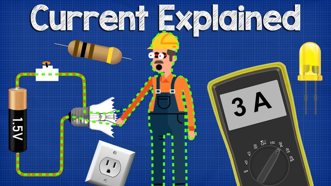
Electrical Current Explained - AC DC, fuses, circuit breakers, multimeter, GFCI, ampere
TLDRThis informative video from engineeringmindset.com explores the fundamentals of electrical current, elucidating the flow of electrons, the role of voltage, and the importance of safety devices. It delves into the historical perspective of current flow, contrasting conventional current with electron flow, and explains the use of AC and DC in various applications. The video also covers the measurement of current using ammeters and the function of fuses and circuit breakers in protecting electrical circuits.
Takeaways
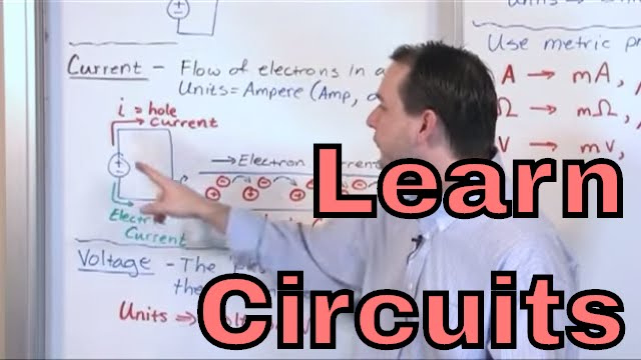
- 🔋 Understanding Electrical Current: Current is the flow of electrons in a circuit, facilitated by materials like copper due to its good conductivity and loosely bound outer electrons.
- 🌐 Copper Wires and Insulation: Copper wires are wrapped in rubber to create an insulator, preventing free electron movement and keeping electricity contained for safe use.
- 💡 The Role of Voltage: Voltage is the driving force for electron flow, akin to water pressure in pipes. It influences the rate of electron movement and is measurable even without current flow.
- 🔄 Conventional vs. Electron Flow: Conventional current (from positive to negative) and electron flow (from negative to positive) are two theories of electricity. Modern understanding supports electron flow, but conventional current is still taught and used.
- 🔌 Types of Current: AC (Alternating Current) changes direction and is used for power transmission, while DC (Direct Current) flows in one direction and is used in electronic devices.
- 📈 Measuring Current: An ammeter or multimeter is used to measure the flow of current in amperes (amps), which is the quantity of electrons passing a point per second.
- 🔥 Ohm's Law and Resistance: Resistors add difficulty to electron flow, reducing current and causing voltage drop and heat generation. The current is consistent throughout a series circuit.
- 🔧 Circuit Protection: Fuses, circuit breakers, and GFCI/RCD devices are safety mechanisms that prevent damage and danger by interrupting the circuit in case of overloads, short circuits, or leakage.
- 💡 LED Current Requirements: LEDs have specific current requirements. Using resistors to limit current prevents damage, with the resistor's ohm value affecting the resulting current flow.
- 🏠 Home Energy Usage: Energy meters can measure voltage, current, and energy consumption of appliances, providing insights into household electricity use and costs.
- 📚 Continuing Education: The script encourages further learning about electricity and electrical engineering, promoting the pursuit of knowledge in these fields.
Q & A
What is electrical current and how is it produced?
-Electrical current is the flow of electrons in a circuit. It is produced when electrons move in a directed manner through a conductive material, such as copper wire, in response to a voltage or electric potential difference.
Why are copper cables commonly used to form electrical circuits?
-Copper cables are popular for forming electrical circuits because copper is an excellent conductor of electricity. The atoms in copper have a loosely bound electron in their valence shell, which is free to move easily within the metal, facilitating the flow of electric current.
What is the purpose of insulating copper wires with rubber?
-Rubber is used to insulate copper wires because it is an insulating material that does not allow free electrons to pass through it. This provides a barrier to keep electricity within the wires and away from people, ensuring safety.
How does applying voltage affect the flow of electrons?
-Applying voltage creates a pushing force, akin to pressure in a water pipe, which compels electrons to move in a specific direction rather than randomly. The higher the voltage, the more electrons are forced to flow, similar to how greater water pressure results in more water flow.
What is the difference between conventional current and electron flow?
-Conventional current is an outdated theory proposed by Benjamin Franklin that suggests electricity flows from positive to negative. However, electron flow, discovered by Joseph Thompson, indicates that electrons actually move from negative to positive. Despite this, the conventional current naming convention is still used in electrical engineering.
How is electrical current measured and what unit is it measured in?
-Electrical current is measured using an ammeter and the flow of current is measured in amperes, often shortened to 'amps'. One ampere is equivalent to one coulomb per second, with a coulomb being approximately six quintillion 242 quadrillion electrons per second.
What are the differences between AC (alternating current) and DC (direct current)?
-AC is a type of electricity where electrons alternate between moving forward and backward in a circuit, similar to the tide. DC, on the other hand, involves electrons flowing in a single direction from one terminal to another, akin to water flowing down a river. AC is typically used for power distribution due to its efficiency and ease of voltage transformation, while DC is used in electronic devices and circuits for its controllability and compactness.
Why do we use resistors in electrical circuits?
-Resistors are used in electrical circuits to restrict the flow of current. They make it more difficult for electrons to pass through, thereby reducing the current. This is useful for protecting components from excessive current and for creating specific voltage drops within the circuit.
How do fuses protect electrical circuits?
-Fuses contain a thin wire that melts when too much current flows through it, breaking the circuit and preventing further damage to electrical components. The fuse acts as a weak point in the circuit, which is designed to fail before any other part of the circuit, and it is relatively inexpensive to replace.
What is the function of a circuit breaker and how does it differ from a GFCI or RCD?
-A circuit breaker automatically opens to break the circuit in the event of an overload or short circuit, providing overload protection. GFCI (Ground Fault Circuit Interrupter) or RCD (Residual Current Device) monitors the current in both the supply and return wires. If the currents are not equal, indicating that electricity is taking an unintended path (like through a person), the device quickly cuts power to prevent electric shock.
How can we calculate the current needed to power a device like a lamp?
-To calculate the current needed to power a device, you can use Ohm's Law, which states that the current (I) is equal to the voltage (V) divided by the resistance (R). For example, if a lamp is rated for 1.5 watts and connected to a 1.5-volt battery, the current would be I = V/R = 1.5V / 1Ω = 1.5 amps.
What is the significance of understanding the concepts of electrical current, voltage, and resistance?
-Understanding electrical current, voltage, and resistance is crucial for designing, analyzing, and troubleshooting electrical circuits. It helps in selecting appropriate components, ensuring the safety and longevity of electrical devices, and optimizing energy efficiency in various applications.
Outlines
🔌 Understanding Electrical Current
This paragraph introduces the concept of electrical current, explaining it as the flow of electrons in a circuit. It emphasizes the importance of using conductive materials like copper for circuit formation due to its loosely bound electrons. The paragraph also discusses the role of insulators, such as rubber, in preventing the free flow of electrons and keeping electricity contained. The video aims to cover the basics of current measurement, types of current, and the function of safety devices in protecting electrical circuits.
🔋 The History and Theories of Electricity
This section delves into the historical understanding of electricity, starting with Benjamin Franklin's early experiments that led to the conventional current theory. It contrasts this with Joseph Thompson's discovery of the electron and the electron flow theory, which revealed electrons moving from negative to positive, contrary to conventional current. The paragraph also touches on the practicality of continuing with conventional current in electrical engineering and the difference between AC (Alternating Current) and DC (Direct Current), highlighting their applications and the ease of converting one to another using rectifiers and inverters.
📏 Measuring and Controlling Current
This part of the script focuses on the practical aspects of measuring and controlling electrical current. It explains the use of ammeters to measure current in amperes and introduces the concept of an amp as a unit of electrical current. The paragraph further discusses the relationship between voltage, current, and resistance, using the example of a simple series circuit with lamps to illustrate how adding more resistance affects the current flow. It also touches on the use of multimeters as versatile tools for electrical engineers.
⚠️ Safety Devices in Electrical Circuits
The final paragraph discusses the importance of safety devices in electrical circuits, such as fuses, circuit breakers, and GFCI/RCDs. It explains the function of each device in protecting circuits from overloads, short circuits, and potential electric shocks. The paragraph provides examples of how these devices work, including the role of a resistor in limiting current flow and the operation of energy meters for monitoring consumption. It concludes with a brief mention of the significance of understanding these concepts for electrical safety and efficiency.
Mindmap
Keywords
💡Electrical Current
💡Copper Cables
💡Voltage
💡Insulator
💡Electron Flow
💡Conventional Current
💡Alternating Current (AC)
💡Direct Current (DC)
💡Ammeter
💡Ohm's Law
💡Resistor
💡Fuses
Highlights
Electrical current is the flow of electrons in a circuit.
Copper cables are used to form circuits due to their excellent conductivity.
Insulators like rubber are used to wrap copper wires to keep electricity within and away from users.
Voltage is the pushing force that drives electrons to move, akin to water pressure in pipes.
The random movement of electrons is not considered a current.
Conventional current theory, proposed by Benjamin Franklin, suggests electricity flows from positive to negative.
Electron flow theory, discovered by Joseph Thompson, indicates electrons actually flow from negative to positive.
AC (Alternating Current) and DC (Direct Current) are two types of electricity, with AC being more suitable for long-distance transmission.
Devices like laptops and mobile phones use DC electricity, which is easier to control and allows for more compact designs.
An ammeter is used to measure the flow of current, with the unit of measurement being amperes or amps.
One amp is equal to one coulomb per second, with a coulomb being approximately six quintillion electrons.
In a series circuit, the current is the same at any point in the circuit.
In a parallel circuit, the total current in the main wire is the sum of the currents in each branch.
Resistors restrict the flow of current, making it harder for electrons to pass through, thus reducing the current.
Fuses protect electrical circuits by breaking the circuit if too much current flows through them.
Circuit breakers automatically open to break the circuit in case of overload or short circuit, providing protection.
GFCIs or RCDs monitor current in supply and return wires, cutting power if an imbalance is detected, protecting against electric shocks.
Transcripts


5.0 / 5 (0 votes)
Thanks for rating: