How 555 timers Work - The Learning Circuit
TLDRIn this episode of 'The Learning Circuit' by element14, Karen dives into the workings of the 555 timer IC, a versatile component popular in hobby electronics. She explains the 8 pins and their functions, including ground, trigger, output, reset, control voltage, threshold, discharge, and VCC connections. The internal components, such as two comparators, a flip-flop, inverter, two transistors, and a voltage divider, are detailed. The script explores how these elements interact to create a timer, oscillator, or flip-flop. Karen also discusses the comparators' roles in setting and resetting the flip-flop, and how the output is generated. The video promises future insights into using the 555 timer in different circuit modes, inviting viewers to join the community for further learning.
Takeaways
- 🌟 The 555 timer is a highly popular IC used in hobby circuits for its versatility as a timer, oscillator, or flip-flop.
- 📍 It is housed in an 8-pin IC with pins serving specific functions such as ground, trigger, output, reset, control voltage, threshold, discharge, and VCC connection.
- 🔍 Inside the 555 timer, there are two comparators, a flip-flop, an inverter, two transistors, and a voltage divider, which are the main components.
- 🔌 The voltage divider, made of three 5kΩ resistors, divides the supply voltage and provides reference voltages to the comparators, possibly contributing to the '555' name.
- ⚡ With a typical VCC range of 4.5 to 16 volts, the voltage divider sets the reference voltages for the comparators, which compare input voltages to these references to output digital signals.
- 🔄 Comparator one outputs high when the voltage at pin 6 (threshold) is above two-thirds of VCC, and comparator two outputs high when the voltage at pin 2 (trigger) is below one-third of VCC.
- 🛑 The flip-flop within the 555 timer is set and reset by the outputs of the comparators, controlling the timer's operation and output.
- 🔁 The flip-flop's output, which is the inverse of Q (not Q), goes through an inverter before being output from pin 3, completing the signal path.
- 🔧 Pin 5 allows for control voltage adjustment, influencing the operation of comparator one and thus the timer's behavior.
- 🔄 Pin 4, when connected to VCC, ensures the transistor is on for the 555 timer to function; grounding it triggers a reset.
- 🔌 Pin 7 is used for discharging external capacitors, which are crucial for timing operations in the 555 timer circuits.
Q & A
What is the 555 timer?
-The 555 timer is a popular integrated circuit (IC) used in hobby circuits that can function as a timer, oscillator, or flip-flop.
How many pins does the 555 timer have?
-The 555 timer has 8 pins, which include ground, trigger, output, reset, control voltage, threshold, discharge, and VCC.
What are the main internal components of the 555 timer?
-The 555 timer consists of two comparators, an SR flip-flop, an inverter, two transistors, and a voltage divider made up of resistors.
What is the purpose of the voltage divider inside the 555 timer?
-The voltage divider inside the 555 timer is made of three 5 kilo-ohm resistors and is used to divide the supply voltage, providing different reference voltages to the comparators.
How does the voltage divider divide the supply voltage (VCC)?
-The voltage divider divides the supply voltage such that the input of comparator 1 gets two-thirds of the VCC, and the input of comparator 2 gets one-third of the VCC.
What is the role of comparators in the 555 timer?
-Comparators in the 555 timer compare the voltages at their inputs and output a digital signal indicating which input has a larger voltage.
How does the flip-flop in the 555 timer operate?
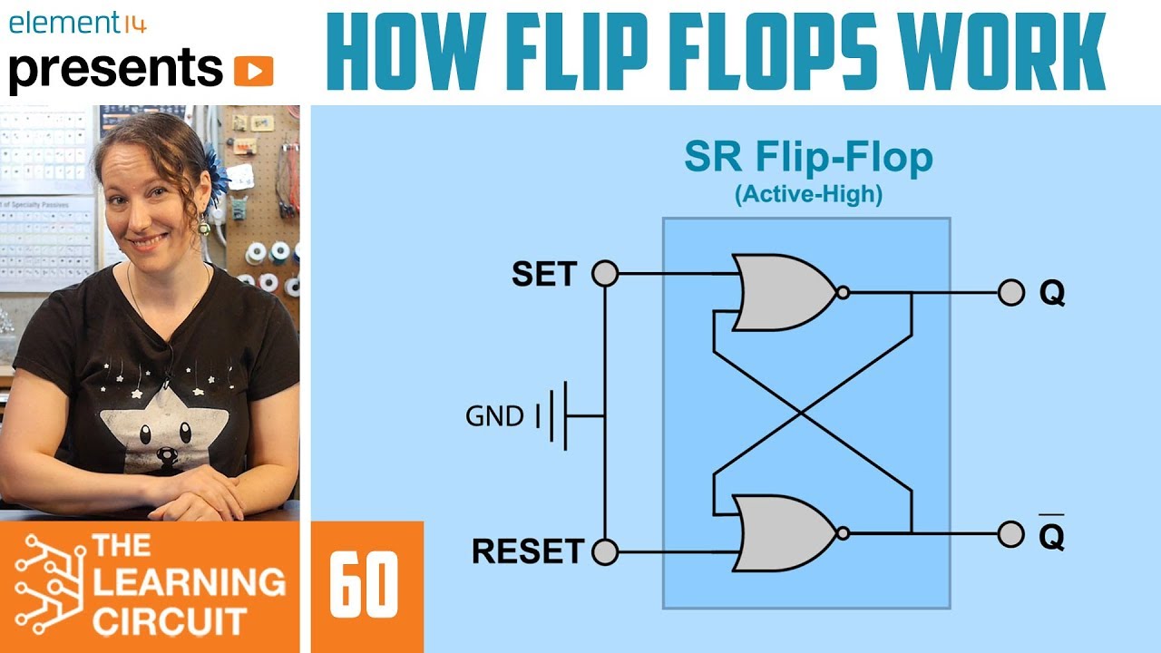
-The flip-flop in the 555 timer has set and reset inputs (S and R). The set input sets the output high, while the reset input resets the output back to low. The flip-flop is active high and only the output not Q is used in the 555 timer.
What happens when the flip-flop is set and reset simultaneously?
-When both the set and reset inputs of the flip-flop are high at the same time, the outputs begin to behave unpredictably, which is considered an invalid state.
What is the function of pin 5 in the 555 timer?
-Pin 5 is the control voltage pin and is used to adjust or control the voltage at the negative input of comparator one, which typically has a voltage that's two-thirds of VCC.
What is the purpose of pin 4 and pin 7 in the 555 timer?
-Pin 4 is used for reset and is usually connected to VCC to keep the transistor on. Pin 7 is the discharge pin and is used with external capacitors to control the charging and discharging process in the timer circuit.
What are the different modes the 555 timer can be used in?
-The 555 timer can be used in various modes such as stable, monostable, and bistable, which will be discussed in future episodes.
Outlines
🛠️ Introduction to the 555 Timer
This paragraph introduces the 555 timer, a versatile integrated circuit (IC) commonly used in hobby electronics. It is highlighted as a switching circuit contained within an 8-pin IC, capable of functioning as a timer, oscillator, or flip-flop. The paragraph details the 8 pins of the 555 timer, explaining their functions and connections, such as pin 1 for ground, pin 2 for trigger, and pin 8 for VCC. The internal components of the 555 timer are also outlined, including two comparators, a flip-flop, an inverter, two transistors, and a voltage divider made up of 3.5 kilo-ohm resistors. The voltage divider's role in dividing the supply voltage and feeding the comparators is explained, along with how the comparators operate based on the voltage levels at their inputs. The flip-flop's function in the 555 timer is also briefly recapped, setting the stage for a deeper exploration of the 555 timer's operation in subsequent content.
🔁 Understanding the 555 Timer's Operation
This paragraph delves deeper into the 555 timer's operation, focusing on the flip-flop's role and the interaction between the comparators and the flip-flop. It explains how the flip-flop is set and reset by the comparators' outputs, with the trigger pin acting as a starting mechanism for the timer. The importance of not having both comparators output high simultaneously to avoid unpredictable behavior is emphasized. The paragraph also describes the signal path from input to output, including the inverter's role and the significance of the output pin. Additional pins such as pin 5 for control voltage, pin 4 for reset, and pin 7 for discharge are discussed, explaining their functions in adjusting the comparator's reference voltage, resetting the circuit, and controlling the charging and discharging of external capacitors, respectively. The paragraph concludes by stating that future content will explore the 555 timer's application in various circuit types and modes, inviting viewers to engage with the community for further learning and support.
Mindmap
Keywords
💡555 Timer
💡Pin Functions
💡Comparators
💡Flip-Flop
💡Voltage Divider
💡Oscillator
💡Monostable and Bistable
💡Trigger
💡Reset
💡Discharge
💡Control Voltage
Highlights
The 555 timer is one of the most popular ICs used in hobby circuits.
The 555 timer can act as a timer, oscillator, or flip-flop.
The 555 timer is an 8-pin IC with specific pin functions.
Pin 1 is for ground, pin 2 is the trigger, and pin 3 is the output for reset.
Pin 5 is for control voltage, pin 6 is the threshold, and pin 7 is for discharge.
Pin 8 is for connecting to VCC.
The 555 timer consists of resistors, transistors, two comparators, a flip-flop, and an inverter.
A voltage divider made of 3 x 5 kilo-ohm resistors divides the supply voltage.
The supply voltage range is typically 4.5 to 16 volts, but VCC is usually between 5 and 15 volts.
Comparators output a digital signal indicating which of its inputs is larger.
The flip-flop has two inputs (set and reset) and two outputs (Q and not Q).
The flip-flop in the 555 timer is active high and only uses the not Q output.
The outputs of the comparators control the flip-flop's set and reset inputs.
Pin 5 can adjust or control the voltage at the negative input of comparator one.
Pin 4 is connected to the base of a transistor that must be on for the 555 to function.
Pin 7 is used with external capacitors to control the timer duration.
The 555 timer's output is controlled by the flip-flop's not Q output and an inverter.
Future episodes will cover the 555 timer's use in various circuit modes like stable, monostable, and bistable.
Transcripts


5.0 / 5 (0 votes)
Thanks for rating: