Resistors in parallel | Circuits | Physics | Khan Academy
TLDRThis educational video script explores the concept of resistors in parallel circuits. It explains how electrons have a choice of paths, leading to a division of current flow, and emphasizes the importance of understanding electron flow versus conventional current direction. The script uses Ohm's law to calculate total current and equivalent resistance in a parallel circuit, demonstrating the process with a practical example involving a 16-volt battery and resistors of 20 ohms and 5 ohms. It concludes by illustrating how the current is distributed through the parallel paths, highlighting the relationship between resistance and current flow.
Takeaways
- 🔌 The script discusses the concept of resistors in parallel, explaining how they function differently from resistors in series.
- 🌈 The instructor uses a new color, magenta, to illustrate the concept of parallel resistors branching off from a single path.
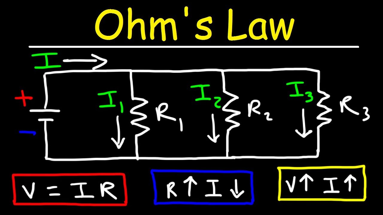
- 🔋 The video script introduces the idea that the current through a parallel circuit can split and recombine, with the total current being the sum of the individual branch currents.
- 🔬 The script emphasizes the importance of understanding electron flow, which is opposite to the conventional current direction from positive to negative.
- ⚡ It explains that in a parallel circuit, the voltage across each resistor is the same, as it would be across any point in an ideal conductor.
- 📐 The script uses Ohm's law (V = IR) to calculate the current through each resistor and the total current in the circuit.
- 🧩 The concept of equivalent resistance in a parallel circuit is introduced, showing that it can be calculated by adding the reciprocals of the individual resistances.
- 📉 The script demonstrates that more current flows through a resistor with lower resistance, as it offers less opposition to the flow of electrons.
- 📝 An example problem is solved in the script, calculating the total current and individual branch currents for a 16V battery with 20 ohm and 5 ohm resistors in parallel.
- 🔍 The script concludes by reinforcing the idea that the sum of the individual branch currents equals the total current in the circuit, providing a practical application of the theory.
- 🚀 The video aims to provide intuition about parallel resistors through both theoretical explanation and practical problem-solving.
Q & A
What is the main topic discussed in the video script?
-The main topic discussed in the video script is the behavior of resistors in parallel circuits.
What is the significance of the color magenta in the script?
-The color magenta is used by the presenter to distinguish a new part of the circuit diagram being discussed.
How does the script describe the flow of electrons in a parallel circuit?
-The script describes the flow of electrons as having a choice at a branch point, with some electrons taking one path and others taking another, eventually recombining at a later point in the circuit.
What is the convention for current flow mentioned in the script?
-The convention mentioned in the script is that current flows from the positive to the negative terminal, although it emphasizes that it's actually the electrons that are moving in the opposite direction.
How is the total current in a parallel circuit related to the currents through individual resistors?
-The total current in a parallel circuit is the sum of the currents through each individual resistor, as explained by the principle that the current entering a branch must equal the current exiting the branch.
What principle is used to determine the equivalent resistance of resistors in parallel?
-The principle used to determine the equivalent resistance of resistors in parallel is that the total resistance is found by taking the reciprocal of the sum of the reciprocals of the individual resistances (1/R_total = 1/R1 + 1/R2 + ...).
How does the script explain the voltage across resistors in a parallel circuit?
-The script explains that the voltage across each resistor in a parallel circuit is the same, as the voltage along any part of an ideal conductor is constant.
What is Ohm's law, and how is it applied in the script?
-Ohm's law states that the current through a conductor between two points is directly proportional to the voltage across the two points and inversely proportional to the resistance between them (V = IR or I = V/R). The script applies Ohm's law to calculate the current through individual resistors in a parallel circuit.
What is the purpose of calculating the equivalent resistance in a parallel circuit?
-The purpose of calculating the equivalent resistance in a parallel circuit is to simplify the circuit to a single resistor that can be used with Ohm's law to find the total current flowing through the circuit.
How does the script illustrate the concept of current distribution in a parallel circuit with an example?
-The script uses an example of a 16-volt battery connected to two resistors, 20 ohms and 5 ohms, in parallel. It calculates the equivalent resistance and then uses Ohm's law to find the total current and the current through each resistor individually.
What conclusion does the script draw about the relationship between resistance and current in a parallel circuit?
-The script concludes that less current flows through the resistor with higher resistance and more current flows through the resistor with lower resistance, as demonstrated by the example with 20-ohm and 5-ohm resistors.
Outlines
🔌 Introduction to Resistors in Parallel
This paragraph introduces the concept of resistors in parallel, contrasting it with the previously discussed series configuration. It explains how an ideal conducting wire branches off to accommodate two resistors, R1 and R2, and emphasizes the electron flow from the negative to the positive terminal, contrary to the conventional current direction. The paragraph sets up the scenario for understanding how current divides and recombines in a parallel circuit, highlighting the importance of recognizing electron flow for a deeper comprehension of circuit behavior.
🔍 Calculating Current and Resistance in Parallel Circuits
The second paragraph delves into the mathematics of parallel circuits, using Ohm's law to explain how current is distributed among parallel resistors. It illustrates that the total current in the circuit is the sum of the currents through each resistor and that the voltage across all components remains constant. The explanation includes deriving the formula for total resistance in a parallel circuit, which is the reciprocal of the sum of the reciprocals of individual resistances. The paragraph also provides an example using a 16-volt battery with two resistors, 20 ohms and 5 ohms, to calculate the equivalent resistance and the total current flowing through the system.
📡 Determining Individual Currents in a Parallel Circuit
The final paragraph focuses on calculating the individual currents through each resistor in a parallel circuit, using the previously determined total resistance and voltage. It demonstrates how to find the current through each resistor (I1 and I2) by applying Ohm's law separately to each component. The example given shows that with a 16-volt source, the current through a 20-ohm resistor is 0.8 amperes, and through a 5-ohm resistor is 3.2 amperes, summing up to the total current of 4 amperes as predicted by the total resistance calculation. This reinforces the understanding of current distribution in parallel circuits and concludes the video script with a practical application of the concepts discussed.
Mindmap
Keywords
💡Resistors in Parallel
💡Current
💡Voltage
💡Ohm's Law
💡Electron Flow
💡Ideal Conducting Wire
💡Total Resistance
💡Equivalent Resistance
💡Coulombs per Second
💡Potential Difference
💡Circuit Topology
Highlights
Introduction to the concept of resistors in parallel and how they function differently than in series.
Explanation of the non-intuitive convention of current flow from positive to negative, contrasting with the actual electron flow.
Demonstration of how electrons have a choice of paths in a parallel circuit, affecting the distribution of current.
Illustration of how the total current in a parallel circuit is the sum of the currents in each branch.
Clarification that the voltage along an ideal wire remains constant, regardless of the circuit's complexity.
Application of Ohm's law to calculate the current through resistors in parallel using the total voltage and resistance.
Derivation of the formula for total resistance in a parallel circuit, 1/R_total = 1/R1 + 1/R2.
Explanation of how to calculate individual branch currents (I1, I2, etc.) using the voltage across each resistor.
Practical example of calculating the total and branch currents in a parallel circuit with a 16V battery and specified resistances.
Use of Ohm's law to find the equivalent resistance of a complex circuit by simplifying it to a single resistor.
Demonstration of how to determine the current through each resistor in a parallel circuit given the total current.
Visual representation of a complex circuit as a simplified equivalent circuit for easier analysis.
Calculation of the current through a 20-ohm resistor (I1) and a 5-ohm resistor (I2) in a parallel circuit.
Insight into why more current flows through the resistor with lower resistance in a parallel circuit.
Verification that the sum of the individual branch currents equals the total current in the circuit.
Conclusion summarizing the key points about resistors in parallel and their behavior in a circuit.
Transcripts


5.0 / 5 (0 votes)
Thanks for rating: