Solving the HARDEST Oxford Physics Admission Question from 2021?
TLDRThis video script delves into solving a complex diffraction problem from the 2021 Oxford Physics Aptitude Test. It explains how to determine the diameter of the spot projected by a pinhole camera using geometric optics and diffraction principles. The presenter constructs ray diagrams, applies the concept of similar triangles, and introduces the diffraction pattern to find the central peak's diameter. The video concludes with calculus to find the pinhole size that yields the sharpest image, assuming small angles for simplicity. It's an educational walkthrough aimed at students preparing for physics exams.
Takeaways
- 📚 The problem involves a pinhole camera setup with a point light source and a small aperture, aiming to determine the diameter of the projected spot.
- 🔍 The solution process begins with constructing a ray diagram to visualize the light paths and the formation of the image.
- 📐 The concept of similar triangles is introduced to establish a relationship between the sides of the triangles formed by the light rays and the pinhole.
- 🧩 The ratio of the sides of the triangles is used to derive an expression for the diameter of the image (S1) in terms of the pinhole diameter (X), the distance from the light source to the pinhole (U), and the distance from the pinhole to the screen (D).
- 🌌 When D is significantly larger than X, diffraction effects come into play, leading to the formation of a diffraction pattern with a central peak.
- 📏 The diameter of the central peak of the diffraction pattern (S2) is approximated using trigonometry and the small angle approximation, resulting in an expression involving D, the wavelength of light (Lambda), and X.
- 🔢 The total diameter of the spot on the screen (S3) is found by combining the effects of the geometric image diameter (S1) and the diffraction pattern diameter (S2), using the Pythagorean theorem.
- 📉 To obtain the sharpest image, a balance must be struck between minimizing S1 to reduce geometric blurring and managing the diffraction effects that become more pronounced with smaller pinholes.
- 📚 The pinhole size that results in the sharpest image is found by minimizing S3 squared, which involves calculus to find the inflection point of the function.
- 🔍 The differentiation of S3 squared leads to an equation that can be solved for the optimal pinhole size (X), considering the relationship between U, D, and Lambda.
- 🎓 The final expression for the optimal pinhole size involves raising the ratio of distances and the wavelength to the power of one-fourth, assuming a small angle approximation for simplicity.
Q & A
What is the main topic of the video script?
-The main topic of the video script is solving a diffraction problem from the 2021 Oxford Physics Aptitude Test, involving pinhole cameras and the calculation of the diameter of the projected spot.
What are the key components of the pinhole camera setup described in the script?
-The key components of the pinhole camera setup are a box with a small aperture, a point light source at a distance 'U', and a screen at a distance 'D' from the aperture, with the aperture's diameter being 'X'.
What principle is initially considered to solve the problem of finding the diameter of the projected spot?
-The principle initially considered is the similarity of triangles, which allows for the calculation of the ratio of the sides of the triangles formed by the light rays passing through the aperture.
How is the ratio of the sides of the triangles expressed in the script?
-The ratio of the sides of the triangles is expressed as (X/2) / U being equal to (S1/2) / (U + D), where S1 is half of the diameter of the projected spot.
What is the significance of the diffraction pattern in the context of the problem?
-The diffraction pattern is significant because it provides the angular range (between -λ/X and +λ/X) within which the central peak of the diffraction pattern occurs, affecting the diameter of the projected spot.
What trigonometric function is used to relate the diameter of the central peak to the diffraction pattern?
-The tangent function is used, with the equation Tan(λ/X) = S2/2D, where S2 is half of the diameter of the central peak and D is the distance to the screen.
What simplification is made to the trigonometric equation for small angles?
-For small angles, the tangent function is approximated by the angle itself, so Tan(λ/X) ≈ λ/X, simplifying the calculation of S2.
What is the formula for the total diameter S3 when combining the effects of S1 and S2?
-The formula for the total diameter S3 is given by the square root of (S1^2 + S2^2), where S1 is the diameter from the geometric optics calculation and S2 is the diameter from the diffraction pattern.
What calculus method is used to find the pinhole size that produces the sharpest image?
-The calculus method used is differentiation, specifically finding the inflection point or minimum of the S3 squared function by setting its derivative equal to zero.
What is the final expression for the pinhole size X that produces the sharpest image?
-The final expression for the pinhole size X that produces the sharpest image is (2D * λ * U) / (U + D)^4, assuming a small angle approximation.
Why is the small angle approximation assumed in the script?
-The small angle approximation is assumed to simplify the differentiation process and avoid dealing with more complex trigonometric functions, making the algebra and calculus more manageable.
Outlines
🔍 Pinhole Camera Diffraction Problem
The script begins with an introduction to a complex diffraction question from the 2021 Oxford Physics Aptitude Test. It involves a pinhole camera setup with a small aperture, a point light source at a distance 'U', and the goal is to determine the diameter of the projected spot on a screen at a distance 'D'. The explanation uses the concept of similar triangles to establish a relationship between the aperture diameter 'X', the distance 'U', and the image diameter 'S1'. The script then delves into diffraction patterns, introducing the angle 'Theta' and its relationship to the wavelength 'Lambda' and the aperture size 'X'. The central peak's diameter is approximated using small angle approximations, leading to a formula for 'S2', the diameter of the diffraction pattern.
📐 Calculating the Optimal Pinhole Size for Sharp Imagery
This paragraph continues the exploration of the pinhole camera problem, focusing on the calculation of the optimal pinhole size that results in the sharpest image. It discusses the trade-off between the size of the image ('S1') and the diffraction effects that become more pronounced with smaller pinholes. The script introduces a formula for the total diameter 'S3' by combining the geometric and diffraction contributions. The goal is to minimize 'S3 squared', which is achieved by differentiating the expression and finding the inflection point. The calculus involved leads to an equation that can be solved to find the pinhole size 'X' that minimizes the total diameter, under the assumption of small angles for simplification.
🧩 Final Calculations and Encouragement for Exam Preparation
The final paragraph wraps up the detailed calculations and provides a solution for finding the pinhole size that minimizes the total diameter 'S3'. It emphasizes the algebraic and calculus steps required to arrive at the formula for 'X', which is expressed in terms of 'D', 'Lambda', 'U', and 'D'. The script acknowledges the complexity of the problem and the assumption of small angles that simplifies the differentiation process. It concludes with encouragement for those preparing for the exam and an invitation for further practice on similar problems.
Mindmap
Keywords
💡Pinhole Camera
💡Diffraction
💡Similar Triangles
💡Ray Diagram
💡Diameter
💡Trigonometry
💡Small Angle Approximation
💡Optimization
💡Calculus
💡Inflexion Point
💡Wavelength
Highlights
Introduction of a hard diffraction problem from the 2021 Oxford Physics Aptitude Test.
Description of a pinhole camera setup with a point light source at a distance U and the diameter of the hole as X.
The goal is to determine the diameter of the spot projected by the light source.
Use of similar triangles to solve the problem, with the sides being X/2 and S1/2.
Expression of the ratio of sides in the smaller triangle as X/2 over U equals S1/2 over (U + D).
Rearrangement to find S1 as X/U times (U + D).
Introduction of diffraction pattern and its relation to the central peak's diameter.
Explanation of the angle Theta in relation to the diffraction pattern and its boundaries at negative Lambda/X and positive Lambda/X.
Construction of a triangle for the diffraction pattern on the screen with angles Lambda/X.
Use of trigonometry to find the relationship between the tangent of Lambda/X and the distances D and D.
Derivation of S2 as 2D times the tangent of Lambda/X, using the small angle approximation.
Assumption that effects A and B can be combined to give a total diameter S3.
Differentiation of S3 squared to find the pinhole size that produces the sharpest image.
Calculation of the derivative of S3 squared and setting it to zero to find the minimum.
Solving for X to minimize S3 squared, resulting in an expression involving U, D, and Lambda.
Discussion on the trade-off between a small pinhole for sharpness and the increased diffraction effects.
Conclusion with the final expression for the pinhole size X that results in the sharpest image.
Assumption of a small angle approximation to simplify the differentiation process.
Final encouragement for those taking the test and an offer for extra practice.
Transcripts
Browse More Related Video
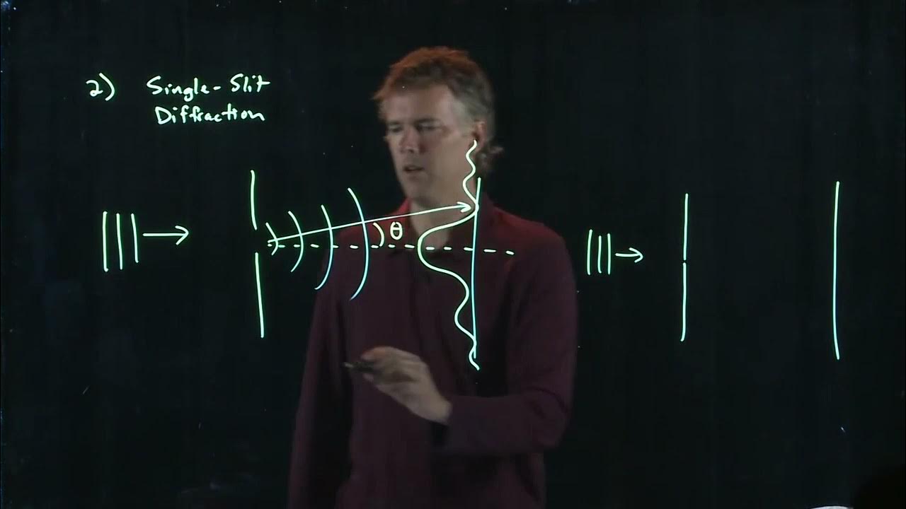
Single Slit Diffraction | Physics with Professor Matt Anderson | M28-16
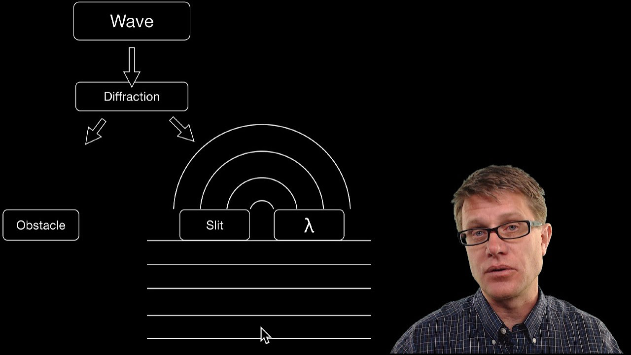
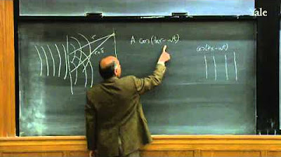
Wave Diffraction
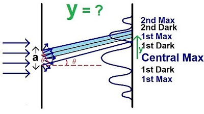
Physics - Diffraction of Light (1 of 4) The Thin Slit
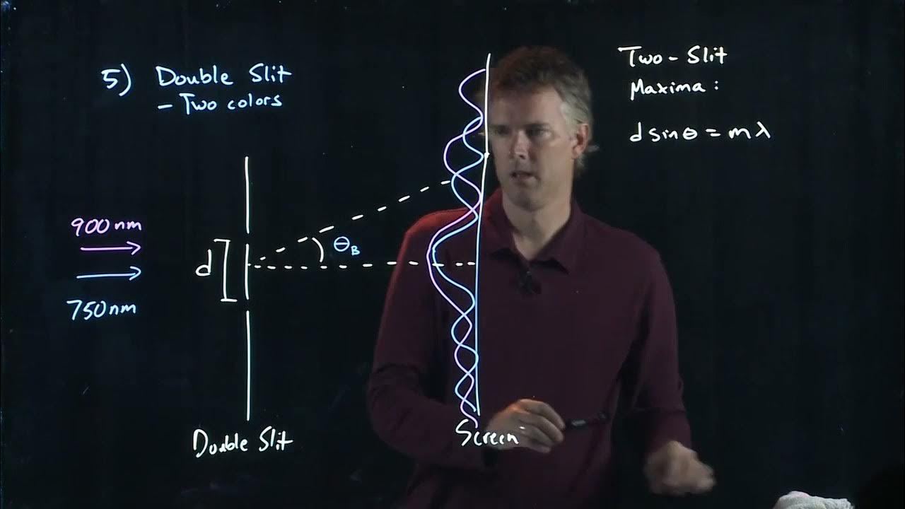
Two Slit Interference | Physics with Professor Matt Anderson | M28-18
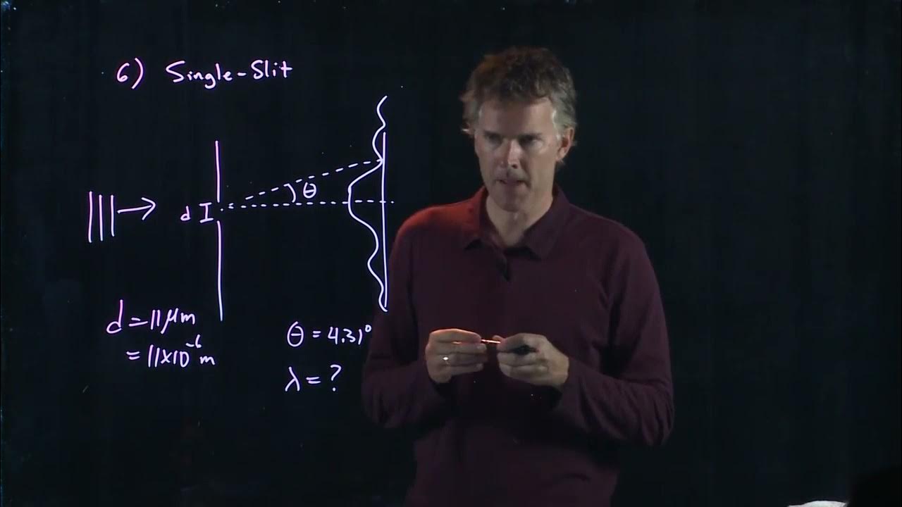
Single Slit Interference | Physics with Professor Matt Anderson | M28-19
18. Wave Theory of Light
5.0 / 5 (0 votes)
Thanks for rating: