Physics - Diffraction of Light (1 of 4) The Thin Slit
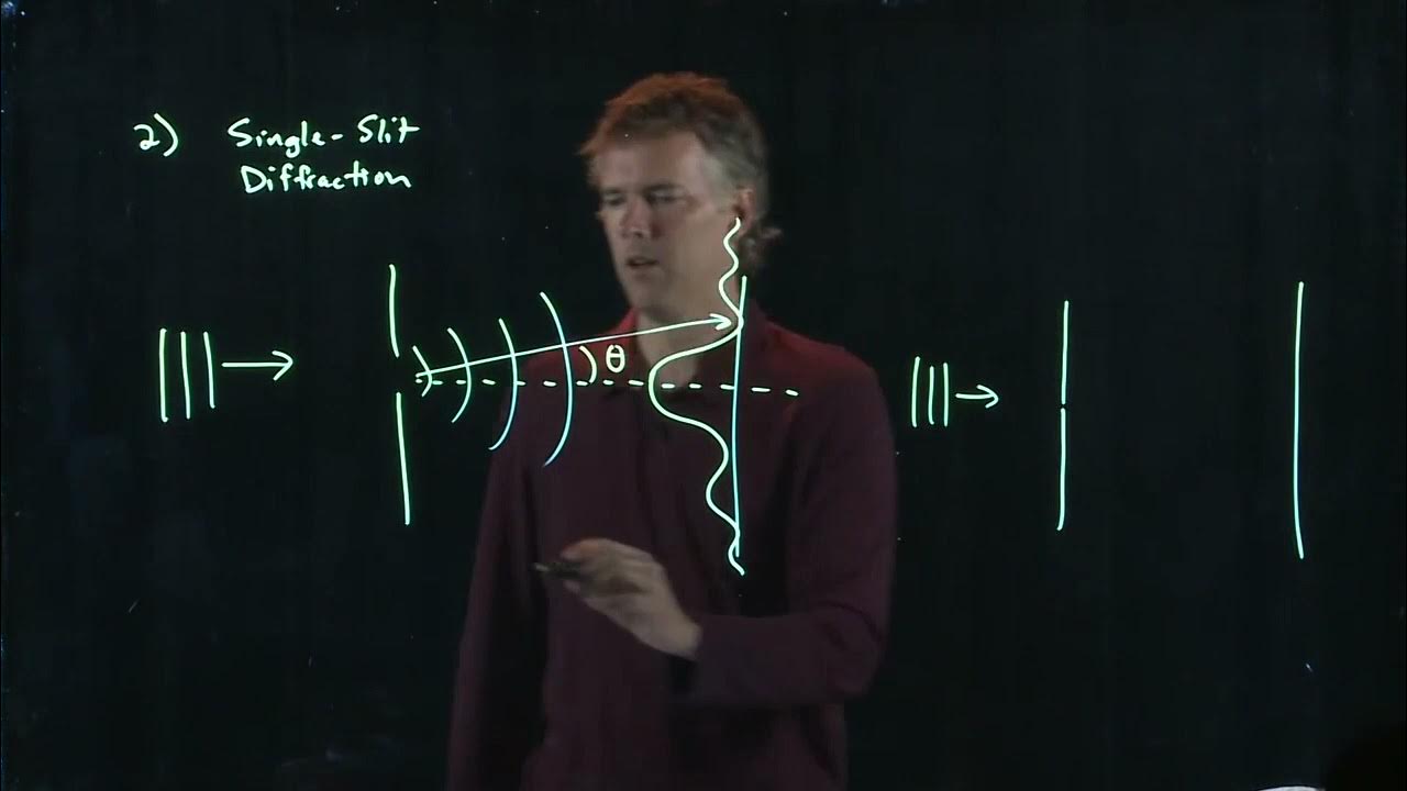
TLDRThis lecture delves into the phenomenon of light diffraction, particularly through a single slit, creating a diffraction pattern distinct from interference. It explains how light passing through a narrow slit forms a central maximum and secondary fringes, both bright and dark. The lecture uses geometrical optics to derive the conditions for these fringes, illustrating how path length differences lead to constructive and destructive interference. It provides a step-by-step calculation for the positions of the first dark and bright spots, using the slit width, wavelength, and distance to the screen, revealing the non-linear relationship between them.
Takeaways
- 🌟 Light interference typically involves multiple sources, but single-slit diffraction is a related phenomenon where light waves bend and interfere as they pass through a narrow opening.
- 🔍 The central maximum in both double-slit and single-slit diffraction patterns is the brightest spot directly opposite the slit, but in single-slit diffraction, it is notably brighter than the side maxima.
- 📏 The formation of dark spots in a diffraction pattern is due to destructive interference between different parts of the light wave that has passed through the slit.
- 📐 The path length difference between rays from different parts of the beam through the slit leads to constructive or destructive interference, creating the pattern of bright and dark fringes.
- 🧭 The condition for the first dark spot in a single-slit diffraction pattern is when the extra distance traveled by a ray is half a wavelength ( \( \frac{\lambda}{2} \) ) out of phase with another ray.
- 📏 The formula to find the position of the first dark spot from the central maximum is \( y = \frac{\lambda L}{a} \), where \( a \) is the width of the slit, \( L \) is the distance to the screen, and \( \lambda \) is the wavelength of light.
- 🔢 For the first bright spot or maximum, the condition involves a path difference that results in constructive interference, with the extra distance traveled by the top ray being \( \frac{\lambda}{2} \) out of phase with the ray one-third into the beam.
- 📏 The formula to find the position of the first bright spot from the central maximum is \( y = \frac{3\lambda L}{2a} \), following the same variables as before but adjusted for the one-third path difference.
- 🔢 The pattern for finding subsequent dark and bright spots involves setting the extra distance traveled by the top ray to be \( \frac{m\lambda}{2} \), where \( m \) is an odd integer for dark spots and an even integer for bright spots.
- 📚 The relationship between the positions of the dark and bright spots is not linear; as the angle increases, the distance between successive spots decreases, following the diffraction pattern's mathematical progression.
Q & A
What is the main topic discussed in the video script?
-The main topic discussed in the video script is the diffraction of light, particularly how it occurs with a single slit and the formation of diffraction patterns.
What is the central maximum in the context of diffraction patterns?
-The central maximum is the bright spot that appears directly across from the slit in a diffraction pattern, similar to the central spot in a double-slit experiment but much brighter.
What causes the appearance of dark spots in a diffraction pattern?
-Dark spots in a diffraction pattern appear due to destructive interference. This happens when various portions of the light beam traveling different paths interfere with each other out of phase, leading to cancellation of light at those points.
How is the path length difference related to the formation of dark spots in a diffraction pattern?
-The path length difference is crucial for the formation of dark spots. When the path length difference equals half a wavelength (λ/2), destructive interference occurs, resulting in a dark spot on the screen.
What is the formula used to calculate the position of the first dark spot in a diffraction pattern?
-The formula used to calculate the position of the first dark spot is y = (λ * L) / (a/2), where y is the distance from the central maximum, λ is the wavelength of light, L is the distance to the screen, and a is the width of the slit.
What is the significance of the slit width in diffraction patterns?
-The slit width (a) plays a significant role in diffraction patterns. A smaller slit width results in more pronounced diffraction effects and a wider range of angles for constructive and destructive interference, affecting the pattern's spacing and intensity.
How does the distance to the screen (L) affect the diffraction pattern?
-The distance to the screen (L) affects the size and spacing of the diffraction pattern. A larger distance to the screen results in a larger pattern, with the fringes (both bright and dark spots) spaced further apart.
What is the condition for the formation of the first bright spot or maximum in a diffraction pattern?
-The first bright spot or maximum is formed when the extra distance traveled by the top ray of the beam equals one-third of the slit width times the sine of the angle (a/3 * sin(θ)) and equals half the wavelength (λ/2), leading to constructive interference.
How can you find the position of the second dark spot in a diffraction pattern?
-The position of the second dark spot can be found by setting the extra distance traveled by the top ray of the beam equal to one-fourth of the slit width times the sine of the angle (a/4 * sin(θ)) and equal to half the wavelength (λ/2), resulting in destructive interference.
What is the general pattern for finding the positions of dark and bright spots in a diffraction pattern?
-The general pattern involves setting the extra distance traveled by the top ray of the beam equal to (a/n) * sin(θ), where n is an odd number for bright spots and an even number for dark spots, and equating it to λ/2 for dark spots or λ for bright spots, then solving for the position y.
Outlines
🌟 Light Diffraction and Central Maximum
This paragraph introduces the concept of light diffraction through a single slit, which results in a diffraction pattern distinct from interference patterns. The central maximum is highlighted as the brightest spot directly opposite the slit. It explains how light waves passing through the slit interfere with each other, creating a pattern with a brighter central maximum and dimmer side maxima. The paragraph delves into the conditions that lead to the formation of dark spots, specifically when the path length difference equals half the wavelength, resulting in destructive interference. It also provides a mathematical formula to calculate the position of the first dark spot from the central maximum, given the slit width, wavelength, and distance to the screen.
🔍 Calculating Diffraction Pattern Positions
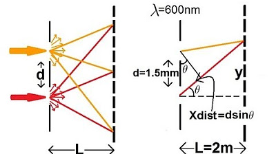
The second paragraph focuses on the mathematical derivation for determining the positions of dark and bright spots in a single-slit diffraction pattern. It uses the example of a 0.01 mm wide slit to calculate the distance to the first dark spot, which occurs at 1.2 cm from the central maximum, given a wavelength of 600 nm and a screen distance of 2 m. The explanation involves setting up the condition for destructive interference and solving for the position 'y' using the relationship between the slit width, wavelength, and the tangent of the angle of diffraction. The paragraph also discusses the calculation for the first bright spot, which is less intense than the central maximum, and explains the pattern for finding subsequent dark and bright spots by adjusting the fraction of the beam considered.
📐 Advanced Diffraction Pattern Analysis
The final paragraph builds upon the previous discussion by explaining how to find the positions of the second dark and bright spots in the diffraction pattern. It describes the process of dividing the beam into four and five equal parts to find these spots, respectively. The conditions for destructive and constructive interference are detailed, with the extra distance traveled by the light rays set equal to half the wavelength (for dark spots) and a fraction of the wavelength (for bright spots). The paragraph provides a step-by-step guide to finding the positions of these fringes, emphasizing the non-linear relationship between them and the central maximum. It concludes with a general formula for finding the positions of subsequent dark and bright spots in the diffraction pattern, illustrating the pattern of increasing the denominator in the sine term for each subsequent spot.
Mindmap
Keywords
💡Diffraction
💡Interference
💡Central Maximum
💡Path Length Difference
💡Wavelength
💡Bright Spots
💡Dark Spots
💡Beam Width
💡Angle Theta
💡Fringes
💡Slit Width
Highlights
Introduction to the concept of light interference and the difference between interference and diffraction.
Explanation of the central maximum in both double slit and single slit systems.
Formation of a diffraction pattern and its contrast with a double slit interference pattern.
The role of the finite width of the light beam in creating a diffraction pattern.
How the path length difference between different portions of the light beam leads to interference.
The condition for the appearance of a dark spot in a diffraction pattern: a/2 sin Theta = Lambda/2.
Calculation of the distance to the first dark spot from the central maximum using the given parameters.
The significance of the slit width (a) in determining the diffraction pattern.
How to find the position of the first bright spot or maximum in a diffraction pattern.
The relationship between the extra distance traveled by the light rays and the formation of bright spots.
The method to calculate the position of the second dark spot in the diffraction pattern.
The process of finding the second maximum or bright spot in the diffraction pattern.
The non-linear relationship between the positions of dark and bright spots in a diffraction pattern.
General formula for finding the positions of dark and bright spots in a diffraction pattern: a/n sin Theta = Lambda/2.
The pattern recognition in calculating fringe positions for diffraction through a single slit.
Practical application of the diffraction pattern in understanding the behavior of light through small apertures.
Transcripts
Browse More Related Video
Physics 60 Interference of Light (4 of 8) Young's Double Slit
Waves part 2 (Double Slit, Single Slit, and Standing Waves)
Single Slit Interference | Physics with Professor Matt Anderson | M28-19
Interference Patterns

Light Is Waves: Crash Course Physics #39
Single Slit Diffraction | Physics with Professor Matt Anderson | M28-16
5.0 / 5 (0 votes)
Thanks for rating: