Physics 15 Torque (24 of 25) More Examples: 6 Forces=? on Crane
TLDRThe video script discusses the application of torque in the context of a heavy crane operation. It explains that the crane is attached to a wall with a hinge at the top (joint A) and a support at B, allowing it to hinge about A and be supported against B. The goal is to determine the forces at points A and B. The script outlines a method to find these forces by summing up torques around point A, which is in equilibrium, and balancing forces in both the X and Y directions. It introduces two forces, 'big mg' for the heavy mass being lifted and 'small mg' for the crane's own weight, with the center of mass of the crane being offset. The script provides a detailed calculation for the force at B, which is the horizontal force required to counteract the torque caused by the crane's and load's weight. The force at A is then determined by considering the forces in the X direction, which must sum to zero, and the forces in the Y direction, which results in the total weight of the crane and load being supported by the pin at A. The video concludes by showing how these techniques can be used to solve for the forces at A and B.
Takeaways
- 🔍 The concept of torque is applied to a simple crane to analyze the forces involved.
- 🏗️ The crane is heavy and handles heavy loads, with a hinge at the top (joint A) and a support at B.
- ⚙️ The force at B is horizontal, while the force at A can be both horizontal and vertical.
- 📐 The crane can hinge about joint A and is supported against B, which are critical points for force analysis.
- ⚖️ The sum of all torques about point A is equal to zero, indicating equilibrium.
- 📏 The distances from the pivot point to the line of action of the forces are crucial for torque calculations.
- 📉 A negative torque is produced by the heavy mass (big mg), and a positive torque by the smaller mass (small mg).
- 🔢 The force at B (F at B) is calculated by summing torques and using the perpendicular distances from the pivot point.
- 🔄 The force at A in the X direction equals the force at B in magnitude but opposite in direction.
- 🚫 The sum of forces in the Y direction equals zero, leading to the calculation of the force at A in the Y direction.
- 🏗️ The entire weight of the crane and load is supported by the pin at A, preventing the crane from falling.
Q & A
What is the primary concept being applied to the crane in the script?
-The primary concept being applied to the crane is torque, which is used to analyze the forces acting on the crane and find the forces at points A and B.
Why is it better to attach the crane to a wall rather than a post?
-It is better to attach the crane to a wall because the crane is handling very heavy loads, and a wall provides more stability and support compared to a post.
What are the two forces that the force at point A can have?
-The force at point A can have both a horizontal force (in the X direction) and a vertical force (in the Y direction).
What is the assumption made about the direction of the horizontal force at point A?
-The assumption made about the direction of the horizontal force at point A is that it will be directed horizontally to the right.
How does the equilibrium condition help in solving for the forces at points A and B?
-The equilibrium condition states that the sum of all torques about point A is equal to zero. This condition, along with the sum of forces in the X and Y directions, helps in solving for the forces at points A and B.
What is the significance of the center of mass of the crane being more to the left and right?
-The significance is that it indicates the crane is heavier at the bottom and lighter near the top, which affects the calculation of torques and the distribution of forces.
What are the two masses referred to as 'big mg' and 'small mg' in the script?
-The 'big mg' refers to the mass of the load being held by the crane, while the 'small mg' refers to the mass of the crane itself.
How is the force at point B calculated in the script?
-The force at point B is calculated by setting up an equation that equates the sum of the torques caused by the weights of the crane and the load to zero, and then solving for the unknown force at B.
What is the total force at B in the X direction after plugging in the numbers?
-The total force at B in the X direction is 759,500 Newtons, which is the torque caused by the two weights trying to rotate the crane about point A.
How is the force at point A in the X direction related to the force at B in the X direction?
-The force at point A in the X direction is equal in magnitude but opposite in direction to the force at B in the X direction, as they are the only two forces acting in the X direction and their sum must be zero for equilibrium.
What is the force at point A in the Y direction, and what does it represent?
-The force at point A in the Y direction is 147,000 Newtons. It represents the entire weight of the crane and the load being held up by the pin at point A, preventing the crane from falling down.
What technique is used to find the forces at points A and B?
-The technique used to find the forces at points A and B involves summing up the torques about a pivot point, summing up all the forces in the X direction, and summing up all the forces in the Y direction.
Outlines
🔧 Analyzing Torque and Forces in a Crane System
This paragraph introduces the concept of torque in the context of a heavy crane. It describes the crane's structure, with a hinge (joint A) and a support (B), and the goal of finding the forces at these points. The forces are categorized into horizontal and vertical components at joint A, and only horizontal at support B. The paragraph outlines the process of summing torques around the pivot point (joint A) to establish equilibrium, considering the weights of the crane (big mg) and its load (small mg), and their respective distances from the pivot. The calculation involves determining the force at B (F_B) by balancing the torques caused by the crane's weight and the load. The final step is to find the force at A in the X direction, which is shown to be equal in magnitude but opposite in direction to the force at B.
📐 Calculating Vertical Force and Summing Forces in X and Y Directions
The second paragraph focuses on calculating the vertical force at joint A and summing the forces in both the X and Y directions to ensure equilibrium. It explains that the sum of the forces in the Y direction equals zero, leading to the calculation of the force at A in the Y direction. This force is determined by adding the weight of the 5,000 kg crane (small mg) and the 10,000 kg load (big mg), resulting in a total force of 147,000 Newtons. This force is what keeps the entire crane and load from falling, supported by the pin at joint A. The paragraph concludes by emphasizing the methodical approach of summing torques about a pivot point and forces in both horizontal and vertical directions to solve for the unknown forces in the system.
Mindmap
Keywords
💡Torque
💡Crane
💡Equilibrium
💡Pivot Point
💡Force at B
💡Force at A
💡Center of Mass
💡Line of Action
💡Perpendicular Distance
💡Summing Torques
💡Newton's Second Law
Highlights
The concept of torque is applied to a simple crane model to determine the forces at two critical points, A and B.
The crane is designed to handle very heavy loads, with the pivot point at A and support at B.
Force at B is identified as a horizontal force, while force at A can be both horizontal and vertical.
The equilibrium condition is used to sum up torques about point A to zero.
Two forces are considered: a large mass (big mg) and a smaller mass (small mg), with the center of mass of the crane being offset.
Torque calculations involve the perpendicular distances from the point of rotation to the line of action of the force.
The force at B is calculated by summing the torques from the large and small masses.
The force at A in the X-direction is determined to be equal in magnitude but opposite in direction to the force at B.
The force at A in the Y-direction is found by summing the forces in the Y-direction to zero, representing the total weight supported by the pin at A.
The entire weight of the crane and load is calculated to be 147,000 Newtons, supported by the pin at A.
Practical application of torque and force summation techniques are demonstrated through the crane model.
The method simplifies the calculation by placing the pivot point at A and summing forces in the X and Y directions.
The force at B is calculated to be 759,500 Newtons, which is the torque caused by the crane's and load's weight.
The force at A in the X-direction is determined to be 759,500 Newtons, illustrating the balance of forces.
The vertical force at A is crucial in preventing the crane from falling and is calculated based on the combined weight of the crane and load.
The transcript provides a step-by-step approach to solving for forces in a mechanical system using torque and force equilibrium principles.
The process emphasizes the importance of considering both horizontal and vertical components of forces in mechanical equilibrium problems.
The solution to the crane model problem demonstrates the real-world application of physics principles in engineering and construction.
Transcripts
Browse More Related Video
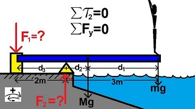
Physics 15 Torque Example 4 (4 of 7) The Diving Board
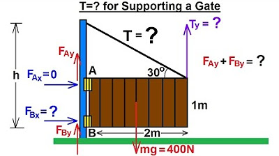
Physics 15 Torque (5 of 27) Tension=? Supporting a Gate
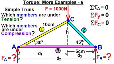
Physics 15 Torque (23 of 25) More Examples: 5 F(A)=? F(B)=? of Simple Truss
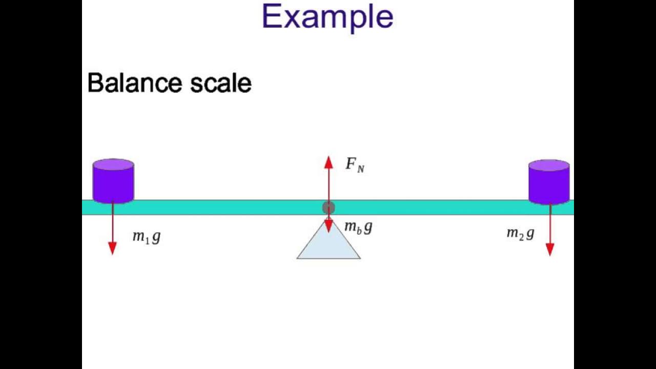
Static Equilibrium: concept
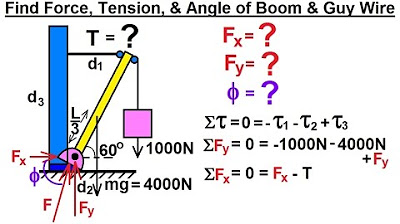
Physics 15 Torque (1 of 27) Boom and Guy Wire
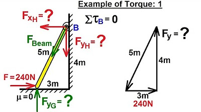
Physics 15 Torque (11 of 27) Example 1: Forces=?
5.0 / 5 (0 votes)
Thanks for rating: