Electronic Filters - Vocademy
TLDRThis script delves into the world of electronic filters, explaining the fundamental role of capacitors and inductors in shaping frequency responses within circuits. It covers how capacitors favor high frequencies and inductors favor low frequencies, and how their combinations in series or parallel configurations can create resonant frequencies, acting as band pass or band reject filters. The script further explores various filter types, including RC and RL filters, and introduces more complex filter designs like T, Pi, and H filters, highlighting their applications in audio systems and the importance of cutoff frequency and Q factor in determining filter performance.
Takeaways
- 📡 Capacitors and inductors have frequency-dependent behavior in AC circuits; capacitors block low frequencies and pass high frequencies, while inductors do the opposite.
- 🔄 When combined in series, a capacitor and inductor can form a resonant circuit that has high impedance except at the resonant frequency, where impedance is low.
- 🔄 In parallel, a capacitor and inductor create a circuit with high impedance at the resonant frequency, allowing frequencies near this point to pass while blocking others.
- 🛠 The addition of resistance to a resonant circuit changes its response, lowering the peak impedance and broadening the frequency range that passes through.
- 🎚 Filters in electronics allow certain frequencies to pass while blocking others, similar to how mechanical or optical filters operate in their respective domains.
- 🔊 In audio systems, filters are used to separate frequencies for different speakers, sending low frequencies to woofers and high frequencies to tweeters for optimal sound reproduction.
- ⚡ The basic building blocks for creating filters are resistors (R), capacitors (C), and inductors (L), which can be arranged to form high pass, low pass, band pass, and band reject filters.
- ⚙️ The cutoff frequency of an RC or RL filter is determined by the formula f_{ ext{Co}} = \frac{1}{2\pi RC} for RC filters and f_{ ext{Co}} = \frac{R}{2\pi L} for RL filters, where the impedance of the capacitor or inductor equals the resistance.
- 📊 The frequency response of filters can be visualized on a graph, with a logarithmic scale showing a steady response that drops off sharply at the cutoff frequency.
- 🔧 The Q factor of a filter, related to its quality, affects the sharpness of the cutoff; a higher Q results in a narrower bandwidth and steeper sides of the filter response curve.
- 🔄 Series and parallel resonant circuits can be combined to create more complex filters with steeper skirts and broader bandwidths, useful for applications requiring both sharp cutoff and wide frequency range.
Q & A
What is the primary function of a capacitor in an AC circuit?
-A capacitor in an AC circuit tends to block low frequencies and pass high frequencies. It blocks DC and has high impedance at low frequencies, which decreases as the frequency increases.
How does an inductor behave in an AC circuit?
-An inductor in an AC circuit tends to block high frequencies and pass low frequencies. It allows low frequencies to pass through but presents high impedance to high frequencies.
What is the resonant frequency in a series LC circuit?
-The resonant frequency in a series LC circuit is the particular frequency at which the impedance of the inductor and capacitor in series is at its minimum, and they have equal reactance.
How do capacitors and inductors behave when connected in parallel?
-When connected in parallel, capacitors and inductors create a circuit that has high impedance at the resonant frequency where the capacitive and inductive reactances are equal, and lower impedance above and below this frequency.
What is an electronic filter and what does it do?
-An electronic filter is a circuit that allows certain frequencies to pass through while blocking others. It can be designed to filter out specific ranges of frequencies in an electronic signal.
Why are different types of speakers needed for different frequency ranges in an audio system?
-Different types of speakers are needed because low frequencies require a large cone to move a lot of air, while high frequencies require a small cone that can move quickly but doesn't need to move as much air.
What is a low pass filter and how is it created?
-A low pass filter is a type of electronic filter that allows low frequencies to pass through and blocks high frequencies. It can be created by placing a resistor and a capacitor in series, with the capacitor across the signal path.
How can you create a high pass filter?
-A high pass filter can be created by placing a resistor and a capacitor in series, but with the capacitor in series with the signal path. This arrangement allows high frequencies to pass through while blocking low frequencies.
What is the significance of the cutoff frequency in a filter?
-The cutoff frequency is the point at which the filter's response drops to 3 dB below the maximum, or where the power transfer is at 50%. It's the frequency where the impedance of the capacitor equals the resistance in the filter circuit.
How can the Q factor of a filter affect its performance?
-The Q factor, or quality factor, of a filter is a measure of its selectivity. A high Q factor indicates a narrow bandwidth and a steeper filter response, while a low Q factor results in a broader bandwidth and a more gradual response.
What are T, Pi, and H filters, and how do they differ from basic RC or RL filters?
-T, Pi, and H filters are configurations that use combinations of inductors and capacitors to create more complex filter characteristics. They differ from basic RC or RL filters by offering different responses and selectivity, which can be adjusted by tweaking the circuit parameters.
Outlines
🔌 Capacitors and Inductors in AC Circuits
This paragraph discusses the behavior of capacitors and inductors in AC circuits. Capacitors block low frequencies and pass high frequencies, while inductors do the opposite. When combined in series, they exhibit high impedance except at the resonant frequency, where impedance is low. In parallel, they show high impedance at the resonant frequency with the capacitive and inductive reactances balancing each other out. The paragraph also touches on how adding resistance affects the circuit's response, broadening the frequency range in parallel circuits and narrowing it in series. The concept of electronic filters, which allow certain frequencies to pass while blocking others, is introduced with an analogy to physical filters for liquids and light.
🎵 Audio Amplifier Systems and Speaker Design
The second paragraph delves into the application of electronic filters in audio amplifier systems, explaining the need for different speaker designs to handle various frequency ranges effectively. Woofers, designed for low frequencies, move more air but require larger cones, while tweeters handle high frequencies with smaller cones that move air quickly. The paragraph outlines a basic concept of a crossover circuit using a resistor and capacitor in series to direct low frequencies to woofers and high frequencies to tweeters, although it acknowledges this is not a practical implementation due to energy waste from the resistor.
⚡ Understanding RC Filters and Their Frequencies
This paragraph explains the fundamentals of RC filters, focusing on how a resistor and capacitor in series affect voltage across them at different frequencies. At low frequencies, the capacitor acts like an open circuit, leading to high voltage across it and low voltage across the resistor. As frequency increases, the voltage across the capacitor decreases, and the resistor's voltage increases. The cutoff frequency is identified as the point where the voltages across both components are equal, and the formula for calculating the cutoff frequency of an RC filter is provided.
📊 Graphing Frequency Response of Filters
The fourth paragraph discusses how to graphically represent the frequency response of filters, using a logarithmic scale to illustrate the steady response until the cutoff frequency is reached, after which the response drops off. The cutoff frequency is defined as the point where the power transfer is 50% (3 dB below the peak), and the importance of this point in determining the filter's performance is emphasized. The paragraph also explains how the orientation of the resistor and capacitor in the circuit determines whether it is a high pass or low pass filter.
🌀 Inductors in Filters and RL Filter Calculations
The role of inductors in filters is explored in this paragraph, which is similar to capacitors but inverse in their effect on frequency—inducing low frequencies and blocking high frequencies. The concept of RL filters is introduced, and the formula for calculating the cutoff frequency of an RL filter is provided, which is based on the inductive reactance being equal to the resistance at the cutoff frequency.
📛 Band Pass and Band Reject Filters with Resonant Circuits
This paragraph introduces band pass and band reject filters, which are created using resonant circuits. A series resonant circuit acts as a band pass filter, allowing the resonant frequency to pass through with high impedance at low and high frequencies. A parallel resonant circuit functions as a band reject filter, blocking the resonant frequency while allowing frequencies above and below to pass. The impact of resistance on the filter's bandwidth and the Q factor is also discussed.
🔄 Exploring Different Resonant Circuit Configurations
The sixth paragraph examines various resonant circuit configurations, such as series and parallel resonant circuits, and their effects on filtering frequencies. It explains how these configurations can be arranged in series or parallel with the signal to create band pass or band reject filters. The resonant frequency's role in determining the filter's behavior is highlighted, along with the impact of resistance on the filter's response curve.
🛠 Advanced Filter Configurations: T, Pi, and H Filters
This paragraph delves into more complex filter configurations, such as T, Pi, and H filters, which offer different characteristics compared to simple LC or RC filters. These configurations can be adjusted to achieve specific filter responses, although the detailed design process is beyond the scope of the discussion. The paragraph also touches on the possibility of combining resonant circuits to create filters with steeper skirts and broader bandwidths.
🔍 Broadening and Steepening Filter Responses
The final paragraph discusses the trade-off between steepness and bandwidth in filters, and how adding resistance can affect the filter's response. It suggests that while a high Q filter has a narrow bandwidth and steep sides, adding resistance can broaden the bandwidth at the expense of steepness. The paragraph concludes by hinting at the possibility of designing filters with both steep skirts and wide bandwidths for specific applications.
Mindmap
Keywords
💡Capacitors
💡Inductors
💡Resonant Frequency
💡Impedance
💡Electronic Filters
💡Cutoff Frequency
💡Audio Amplifier System
💡Reactance
💡RL and RC Filters
💡Bandwidth
💡Q Factor
Highlights
Capacitors tend to block low frequencies and pass high frequencies in AC circuits, while inductors do the opposite.
Inductors and capacitors in series exhibit a resonant frequency where impedance is at its minimum.
Parallel combination of inductors and capacitors results in high impedance at the resonant frequency.
Filters can be designed to pass or block specific frequencies, similar to how physical filters work.
Audio amplifier systems use filters to separate low and high frequencies for woofers and tweeters respectively.
RC series circuit demonstrates how low frequencies create high voltage across the capacitor and low voltage across the resistor.
High frequencies in an RC series circuit result in low voltage across the capacitor and high voltage across the resistor.
The concept of a crossover circuit to divert high frequencies to tweeters and low frequencies to woofers is introduced.
Practical limitations of using resistors in crossover circuits due to energy wastage are discussed.
Introduction to the idea of electronic filters, which allow certain frequencies to pass while blocking others.
Explanation of how to create a low pass filter using a resistor and capacitor in parallel.
The formula for calculating the cutoff frequency of an RC filter is derived as 1 / (2πRC).
Cutoff frequency is defined as the point where power transfer drops by three decibels or 50 percent.
Filters can be designed as high pass, low pass, band pass, or band reject based on circuit configuration.
RL filters, similar to RC filters, use inductors and resistors to create high pass and low pass filters.
Resonant circuits, both series and parallel, can create band pass or band reject filters depending on their configuration.
T, Pi, and L filters are introduced as more complex configurations that can be adjusted for specific filter characteristics.
H filters, resembling the letter H, are mentioned as another advanced filter configuration.
The impact of resistance on filter Q factor and bandwidth is explained, affecting the steepness and width of the filter response.
Complex filters combining series and parallel resonant circuits can achieve both steep skirts and a wide bandwidth.
Transcripts
Browse More Related Video
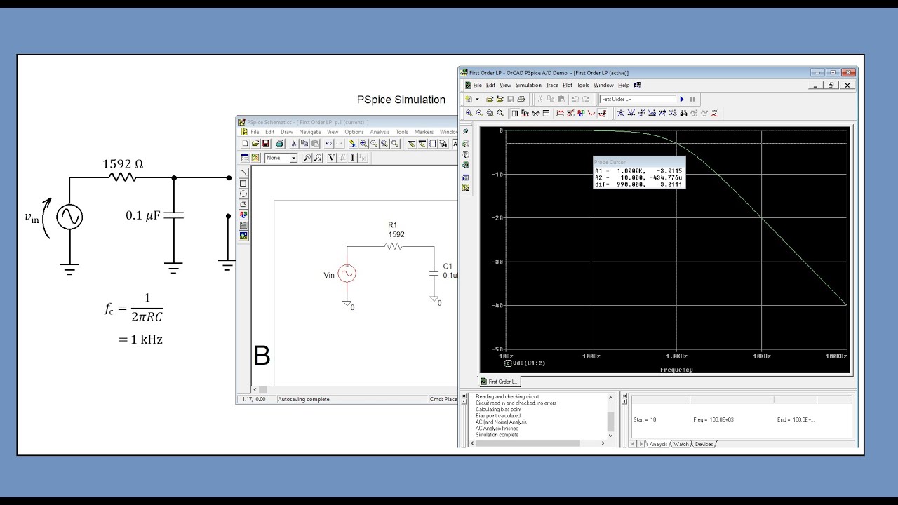
Topic 26: Bode Plots (and a little PSpice)
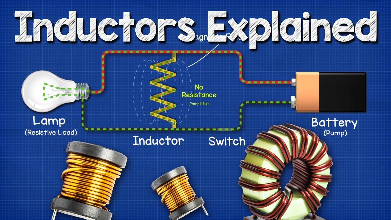
Inductors Explained - The basics how inductors work working principle
12. LCR Circuits—DC Voltage
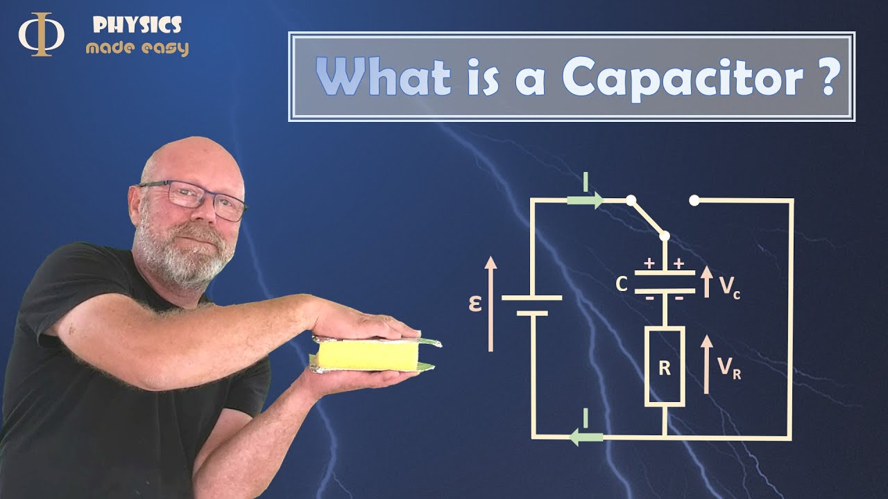
What is a Capacitor? (Physics, Electricity)
02 - Overview of Circuit Components - Resistor, Capacitor, Inductor, Transistor, Diode, Transformer
All electronic components names, functions, testing, pictures and symbols - smd components
5.0 / 5 (0 votes)
Thanks for rating: