Ray Diagrams - Mirrors
TLDRIn this AP Physics essentials video, Mr. Andersen explains the concept of ray diagrams for mirrors, focusing on plane, concave, and convex mirrors. He demonstrates how light reflects off these surfaces to create images, detailing the process of drawing ray diagrams to determine the location and nature of the images formed. The video also discusses real and virtual images, the importance of the angle of incidence and reflection, and uses a simbucket simulation to validate the concepts. The aim is to help students understand how mirrors work and how to apply this knowledge to practical situations, such as using mirrors to see one's whole image or observing the effects of different mirror types on image size and orientation.
Takeaways
- 🌌 Telescopes with mirrors, like the European Extremely Large Telescope, gather more light to provide detailed images of celestial bodies.
- 🔍 The script covers three types of mirrors: plane, concave, and convex, each producing different types of images through reflection.
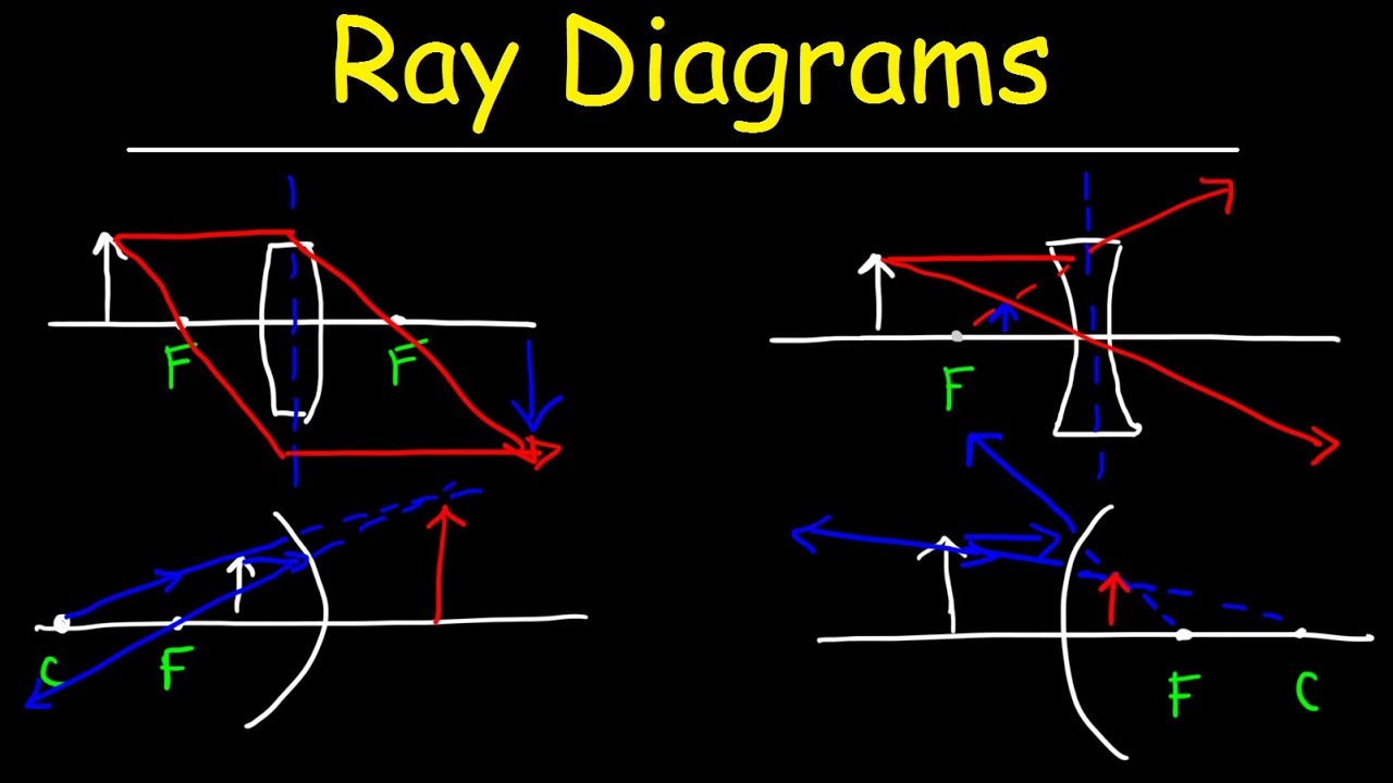
- 📐 Ray diagrams are a method to visualize and determine the path of light reflecting off mirrors and where the image will form.
- 🤔 The script challenges viewers to identify which selfie was taken using a mirror by observing the orientation of details like a shirt.
- 🪞 Plane mirrors create virtual images that are upright and the same size as the object, with the image appearing behind the mirror.
- 🔄 The rule of reflection states that the angle of incidence is equal to the angle of reflection, which is used to draw ray diagrams.
- 🕶️ When standing in front of a plane mirror, the reason a shirt appears backwards is due to the reflection of the plane into the mirror, not left-right reversal.
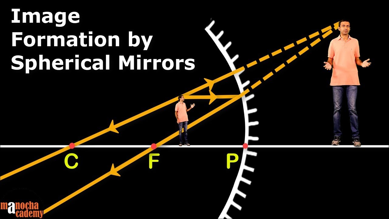
- 🔍 Concave mirrors can produce real, inverted, and smaller images when the object is outside the focal point, and virtual, upright, and larger images when inside the focal length.
- 🛑 Convex mirrors always produce virtual, upright, and smaller images, commonly used in applications like rearview mirrors on buses for wider field of view.
- 📏 The size of the mirror needed to see a full image in a plane mirror is surprisingly small, only half the height of the person, due to the reflection properties.
- 📚 The script encourages practice and verification of ray diagrams using simulations or physical mirrors to ensure understanding of mirror reflections.
Q & A
What is the main topic of Mr. Andersen's AP Physics essentials video 121?
-The main topic of the video is ray diagrams drawn from mirrors, explaining how light is reflected off mirrors to create images.
Why are large telescopes like the extraordinarily large telescope being constructed?
-Large telescopes are being constructed to gather more light, which allows for better and more detailed images of celestial objects like Jupiter.
What are the three types of mirrors discussed in the video?
-The three types of mirrors discussed are plane mirrors, concave mirrors, and convex mirrors.
How can ray diagrams help in understanding mirror reflections?
-Ray diagrams can help determine where the light rays go upon hitting a mirror, allowing us to figure out the location, nature (real or virtual), and size of the image formed.
What is the rule for reflection mentioned in the video?
-The rule for reflection is that the angle of incidence, which is the angle between the normal and the incoming ray, is equal to the angle of reflection.
How does Mr. Andersen demonstrate the concept of reflection using selfies?
-Mr. Andersen uses selfies taken with both the front-facing and rear-facing camera to illustrate how images appear reversed or normal due to the reflection off a plane mirror.
What is the difference between a real image and a virtual image in the context of mirrors?
-A real image is formed where actual light rays converge and can be projected onto a screen, whereas a virtual image is formed where the extensions of the reflected rays appear to converge and cannot be projected onto a screen.
Why does Mr. Andersen suggest drawing a ray diagram for a plane mirror is simple?
-Drawing a ray diagram for a plane mirror is simple because it involves drawing a virtual image on the opposite side of the mirror and ensuring that the angle of incidence equals the angle of reflection.
What happens when an object is placed at the center of curvature of a concave mirror?
-When an object is placed at the center of curvature of a concave mirror, the image formed is the same size as the object, inverted, and located at an infinite distance from the mirror.
How does the size and orientation of the image change when an object is moved inside the focal length of a concave mirror?
-When an object is moved inside the focal length of a concave mirror, the image becomes larger in size, upright, and virtual, meaning it appears on the same side of the mirror as the object.
What is the purpose of the focal point in drawing ray diagrams for concave mirrors?
-The focal point is used in ray diagrams for concave mirrors to determine the path of light rays after they reflect off the mirror. Rays parallel to the mirror will pass through the focal point after reflection.
How does a convex mirror differ from a concave mirror in terms of image formation?
-A convex mirror forms a virtual image that is upright and smaller in size compared to the actual object, due to the light rays diverging after reflecting off the mirror's curved surface.
What practical application of convex mirrors is mentioned in the video?
-Convex mirrors are used in vehicles like buses for rearview purposes, providing a wider field of view with a reduced image size, which helps drivers see more of the area behind them.
How does Mr. Andersen validate the concepts taught in the video?
-Mr. Andersen uses a simbucket simulation to ensure that the ray diagrams and concepts taught match up with the actual behavior of light and mirrors.
Outlines
🔭 Introduction to Ray Diagrams and Mirrors
Mr. Andersen introduces the concept of ray diagrams for mirrors, explaining how telescopes use mirrors to capture light and create detailed images of celestial bodies like Jupiter. He discusses the European construction of an extraordinarily large telescope with a massive mirror to gather more light. The video covers three types of mirrors: plane, concave, and convex, and explains the use of ray diagrams to determine the location and nature of the image formed by these mirrors. The reflection rule that the angle of incidence equals the angle of reflection is also highlighted.
📐 Understanding Plane and Concave Mirrors
The paragraph delves into the specifics of drawing ray diagrams for plane and concave mirrors. For a plane mirror, the process involves drawing a virtual image on the opposite side of the mirror, equal in distance from the mirror as the object, and using the angle of incidence to determine the reflection. The summary explains how the virtual image appears reversed due to the reflection of the plane into the mirror. For concave mirrors, the explanation includes defining the center of curvature and focal point, and using specific rays to determine the location and characteristics of the real image formed. The behavior of the image changes as the object moves from outside to inside the focal length, resulting in different sizes and orientations of the image.
🔍 Exploring Convex Mirrors and Practical Applications
This section focuses on convex mirrors, starting with the drawing of a ray diagram that involves reflecting a parallel ray through the focal point on the mirror's inner side. The explanation covers how the angle of incidence equals the angle of reflection to determine the image's location. Convex mirrors always produce virtual, upright, and reduced-size images. The paragraph concludes with a practical example of convex mirrors used in buses to allow drivers to see a wider field of view, with images appearing smaller but upright.
Mindmap
Keywords
💡Ray diagrams
💡Mirrors
💡Concave mirror
💡Convex mirror
💡Plane mirror
💡Reflection
💡Focal point
💡Center of curvature
💡Virtual image
💡Real image
💡Simbucket simulation
Highlights
Introduction to ray diagrams for mirrors in AP Physics essentials video 121.
Explanation of how telescopes made of mirrors, specifically concave mirrors, capture light to create detailed images of celestial bodies like Jupiter.
Mention of the extraordinarily large telescope being constructed by Europeans, emphasizing the size with a human for scale.
Discussion on the three types of mirrors: plane, concave, and convex, and their roles in creating images.
Ray diagrams as a method to determine the location and nature of images formed by mirrors.
Fundamental rule of reflection: the angle of incidence equals the angle of reflection.
Demonstration of selfies taken with a mirror and without, to illustrate differences in image formation.
Ray diagram drawing technique for a plane mirror, including the concept of virtual images.
Explanation of why a shirt appears backward in a mirror image due to reflection of the plane into the mirror.
Practical exercise on determining the size of a mirror needed to see a whole image using a plane mirror.
Introduction to concave mirrors, their structure, and how they create real, inverted, and smaller images.
Ray diagram for a concave mirror with the object at the center of curvature, resulting in a same-sized, inverted image.
Behavior of images in a concave mirror when the object is inside the focal length, leading to a virtual, upright, and larger image.
Introduction to convex mirrors, their structure, and how they create virtual, upright, and smaller images.
Practical application of convex mirrors on buses to provide a wider field of view with diminished image sizes.
Use of a simbucket simulation to validate ray diagrams and understand mirror image formation.
Encouragement for viewers to practice drawing ray diagrams for different types of mirrors to solidify understanding.
Transcripts
Browse More Related Video
Spherical Mirrors
Ray Diagrams

Concave Mirrors and Convex Mirrors Ray Diagram - Equations / Formulas & Practice Problems

GCSE Physics - Reflection #62

Reflection & its Types | Laws of Reflection | Physics | Letstute

What are Real and Virtual Images? |Light Reflection in a Plane Mirror | Physics | Science | LetsTute
5.0 / 5 (0 votes)
Thanks for rating: